
Models CR-V
1. Clearances are checked on a cold engine (temperature not higher than 38°С).
2. The piston of the cylinder whose valve clearances are being checked must be at TDC on the compression stroke.
3. Remove the cylinder head cover and camshaft belt top cover.
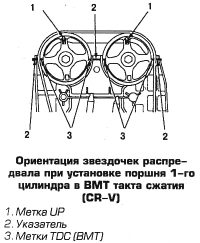
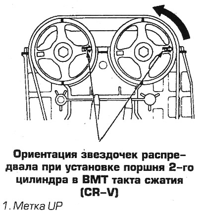
4. Set the piston of the 1st cylinder to the TDC of the compression stroke by turning the crankshaft counterclockwise. The white mark on the crankshaft pulley should align with the pointer on the camshaft belt cover. The UP marks on the camshaft sprockets must face up and the TDC marks (TDC) must align with the marks on the split plane of the cylinder head cover.
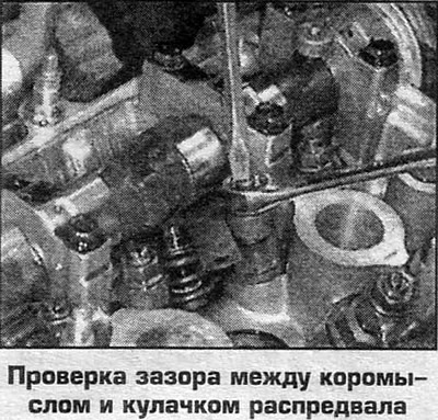
5. Check the intake valve clearances with a feeler gauge inserted between the rocker arm and the camshaft cam. To do this, first insert a 0.08 mm feeler gauge. If the probe does not pass, then the gap should be adjusted. If this probe goes through, then lay the probe 0.15 mm. If this feeler gauge does not pass through the gap, then the gap is correct, otherwise the gap should be adjusted.
6. For CR-V model, normal intake valve clearance is 0.08-0.12mm.
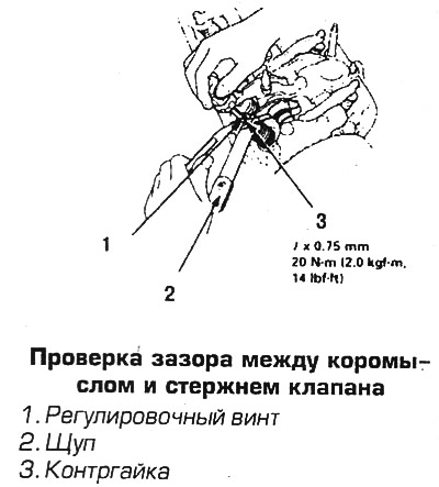
7. To adjust the inlet valves, do the following. Loosen the lock nut, and by turning the screw, increase the gap so that a 0.1 mm feeler gauge can be inserted. While holding the locknut, tighten the screw until you feel a slight resistance, the feeler gauge should pass with little effort. While holding the screw, tighten the locknut and check the clearance.
8. To adjust the intake valves, do the following. Loosen the lock nut, and by turning the screw, increase the gap so that a 0.1 mm feeler gauge can be inserted. While holding the locknut, tighten the screw until you feel a slight resistance, the feeler gauge should pass with little effort. While holding the screw, tighten the locknut and check the clearance.
9. Check up backlashes of final valves. To do this, lay a 0.15 mm feeler gauge between the rocker arm and the camshaft cam. If the probe does not pass, then the gap should be adjusted. If this probe goes through, then lay the probe 0.22 mm. If this probe does not pass in the gap, then the gap is correct, otherwise the gap should be adjusted.
10. For CR-V model, normal clearance for exhaust valves is 0.16-0.20mm.
11. To adjust the exhaust valves, do the following. Loosen the lock nut, and by turning the screw, increase the gap so that a 0.18 mm feeler gauge can be inserted. While holding the locknut, tighten the screw until you feel a slight resistance, the feeler gauge should pass with little effort. While holding the screw, tighten the locknut and check the clearance.
12. Repeat the procedure for the remaining valves in this cylinder.
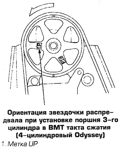
13. Turning the crankshaft counterclockwise, check and adjust the clearances in the valves of the 3rd cylinder, then in the valves of the 4th and, finally, in the valves of the 2nd cylinder.
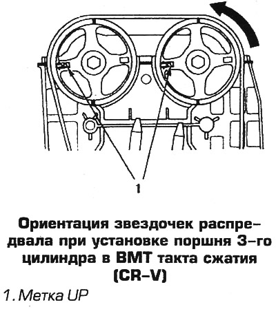
14. When the piston of the 3rd cylinder is set to TDC of the compression stroke, the UP marks on the camshaft sprockets should be facing left horizontally.
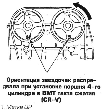
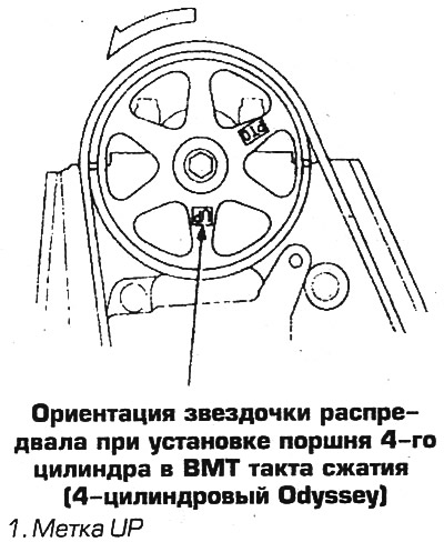
15. When the piston of the 4th cylinder is set to the TDC of the compression stroke, the UP marks on the camshaft sprockets should be facing down, and the TDC marks (TDC) must be aligned with the split plane of the cylinder head cover.
16. When the piston of the 2nd cylinder is set to the TDC of the compression stroke, the UP marks on the camshaft sprockets should be turned to the right horizontally.
17. After adjusting the valves, check the tightening of the crankshaft pulley bolt, if necessary, tighten the bolt with a torque of 117 Nm.
 |  |
 |  |
 |  |
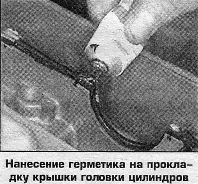
18. Install the removed parts. Establish a cover of a head of cylinders on hermetic.
Odyssey with 4-cylinder engine
1. Clearances are checked on a cold engine (temperature not higher than 38°С).
2. The piston of the cylinder whose valve clearances are being checked must be at TDC on the compression stroke.
3. Remove the cylinder head cover and camshaft belt top cover.
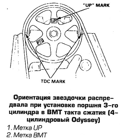
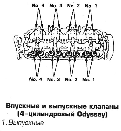
4. Set the piston of the 1st cylinder to the TDC of the compression stroke by turning the crankshaft counterclockwise. The white mark on the crankshaft pulley should align with the pointer on the camshaft belt cover. The UP marks on the camshaft sprockets must face up.
5. Check the intake valve clearances with a feeler gauge inserted between the rocker arm and valve stem. The clearance for intake valves is 0.26 mm, for exhaust valves - 0.30 mm.
6. Check up a backlash for inlet valves execute in a following order. Insert a 0.24 mm feeler gauge between the rocker arm and valve stem. If the probe does not pass, then the gap should be adjusted. If this probe goes through, then lay the probe 0.28 mm. If this feeler gauge does not pass through the gap, then the gap is correct, otherwise the gap should be adjusted.
7. To adjust the inlet valves, do the following. Loosen the lock nut, and by turning the screw, increase the gap so that a 0.26 mm feeler gauge can be inserted. While holding the locknut, tighten the screw until you feel a slight resistance, the feeler gauge should pass with little effort. While holding the screw, tighten the locknut and check the clearance.
8. Check the clearance for the exhaust valves in the following order. First, lay a 0.28 mm feeler gauge between the rocker arm and the valve stem. If the probe does not pass, then the gap should be adjusted. If this probe goes through, then lay the probe 0.33 mm. If this feeler gauge does not pass through the gap, then the gap is correct, otherwise the gap should be adjusted.
9. To adjust the exhaust valves, do the following. Loosen the lock nut, and by turning the screw, increase the gap so that a 0.30 mm feeler gauge can be inserted. While holding the locknut, tighten the screw until you feel a slight resistance, the feeler gauge should pass with little effort. While holding the screw, tighten the locknut and check the clearance.
10. Check the clearances of the exhaust valves.
11. Repeat the procedure for the remaining valves in this cylinder.
13. Turning the crankshaft counterclockwise, check and adjust the clearances in the valves of the 3rd cylinder, then in the valves of the 4th and, finally, in the valves of the 2nd cylinder.
14. When the piston of the 3rd cylinder is set to TDC of the compression stroke, the UP marks on the camshaft sprockets should be facing left horizontally.
15. When the piston of the 4th cylinder is set to the TDC of the compression stroke, the UP marks on the camshaft sprockets should be facing down, and the TDC marks (TDC) must be aligned with the split plane of the cylinder head cover.
16. When the piston of the 2nd cylinder is set to the TDC of the compression stroke, the UP marks on the camshaft sprockets should be turned to the right horizontally.
17. After adjusting the valves, check the tightening of the crankshaft pulley bolt; if necessary, tighten the bolt with a torque of 245 Nm.
18. Install the removed parts. Establish a cover of a head of cylinders on hermetic. Tighten the cover bolts to 9.8 Nm.
 |  |
 |  |
Odyssey V6
1. Clearances are checked on a cold engine (temperature not higher than 38°С).
2. Designate and disconnect air ducts and vacuum hoses from a throttle branch pipe.
3. Remove covers of coils of ignition and an overlay of a cover of a head of cylinders.
4. Disconnect the throttle and cruise control cables from the throttle.
5. Remove the suction manifold (see Chap. 3).
6. Remove covers from both heads of cylinders.
7. Remove the camshaft belt top cover.
8. Set the piston of the 1st cylinder to the TDC of the compression stroke by turning the crankshaft clockwise. The mark on the crankshaft pulley should align with the pointer on the oil pump cover. Mark 1 on the camshaft sprocket must be facing up and aligned with the TDC indicator on the back cover of the toothed belt.
9. Check up backlashes on cores of valves of 1st cylinder, holding a yoke. The clearance for intake valves is 0.20-0.24 mm, for exhaust valves - 0.28-0.32 mm.
10. To adjust the clearance, loosen the locknut and turn the screw to set the clearance. While holding the screw, tighten the locknut to 20 Nm and check the clearance.
11. Turn the crankshaft clockwise until mark 4 on the camshaft sprocket aligns with the pointer on the back cover of the toothed belt.
12. Check and, if necessary, adjust the clearances on the valve stems of the 4th cylinder.
13. Next, turning the crankshaft and aligning the marks 2,5,3 and 6 on the camshaft sprocket with the pointer on the rear cover, check the clearances and, if necessary, adjust the valves of the 2,5,3 and 6th cylinders.
14. Install all removed parts. Check the tightness of the crankshaft pulley bolt, if necessary, tighten the bolt with a torque of 245 Nm.