If the valve clearance is too large, some of the cam lift is used in removing the excess clearance so that the valves will not open sufficiently. Under these conditions, the valves become noisy as they work out excessive clearance, and the engine as a whole runs poorly, since less fuel-air mixture will enter the cylinders. Exhaust valves will not open enough to allow full gas to escape from the cylinder; residual pressure (back pressure) will prevent the next portion of the air-fuel mixture from entering.
If the valve clearance is too small, the intake and exhaust valves will not fully seat on the cylinder head when closed. This causes internal leakage in the cylinder and prevents some heat from being transferred to the cylinder head for cooling. As a result, the engine will run poorly (due to gas leakage from the combustion chamber), and the valves will overheat and deform (as they cannot transfer heat unless they are firmly in contact with the seat in the cylinder head).
All valve adjustments should be as accurate as possible, it is better to have a slightly looser valve fit than a slightly tighter one, as the result of overly tight fitting is valve scorching.
Adjustment
The valve clearance must always be adjusted when the engine is cold. The temperature of the cylinder heads must be below 38°C. This usually means that the engine must be allowed to cool for at least 3 hours after operation. Refrigeration during the night is the best option. If valve adjustment is done as part of normal or after-mileage service, do this work before the engine is warm to check ignition timing or idle.
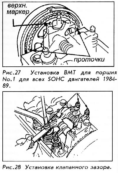
Valve position - intake, exhaust and auxiliary (if used) - will depend on the type of engine. As a guide, the intake valves are always aligned with the intake manifold ports. The exhaust valves align with the exhaust manifold pipes.
Adjusting the valves requires positioning cylinder #1 at TDC, then rotating the engine to a certain other exact position. Rotate the engine using the socket on the crankshaft pulley. (This pulley is the lowest pulley on the engine). It is much easier to rotate the engine if the spark plugs are removed first, thereby reducing the compression in the cylinders. Always rotate the motor in a counter-clockwise direction as viewed from the end of the pulley.
If you miss the mark on this spin, then keep spinning in the same direction until the mark has gone full circle. Reverse rotation can cause the toothed belt to jump or sag, risking damage to the engine upon subsequent start-up. Remember that cylinder #1 is closest to the end of the pulley.
The engine is at TDC Number 1 if ALL of the following are true:
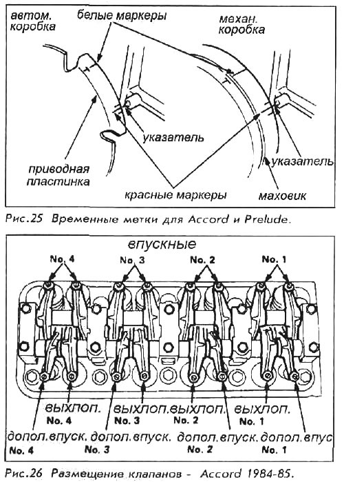
- The TDC mark on the flywheel matches the pointer on the timing inspection window on the back of the engine. The TDC mark is usually white; and never red.
- The distributor rotor points to the spark plug cap or wire Number 1. Mark the cap with the wire number, then remove the cap.
- The alignment marks on the camshaft pulley are located and aligned as indicated for the individual procedure.
- The rocker arms for at least one of the valves on the Number 1 cylinder are loosened; cam points or lugs do not exert pressure on the rocker arms.
1984-1989 Accord, 1984-1987 Prelude, 1988-1990 SOHC Prelude
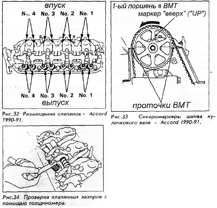
All engines on these vehicles use a single overhead camshaft (SOHC). One cam serves 12 or 16 valves. Engines on the 1984-85 Accord use 2 intake valves, 1 exhaust and 1 auxiliary valve per cylinder. The auxiliary valves are located on the side of the exhaust valve and are smaller than the other valves. Other vehicles use the same but without the auxiliary valve.
Valve clearances are:
- Inlet: 0.12-0.17mm
- Outlet: 0.25-0.30mm
- Auxiliary: 0.12-0.17mm
1. With the ignition off, remove the valve cover.
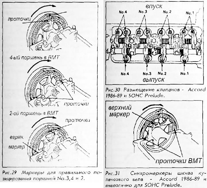
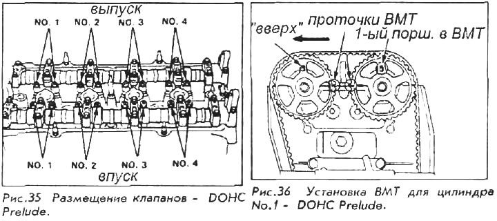
2. Set the engine to the appropriate TDC for cylinder No. 1. UP label (top) on the camshaft pulley should be at the top of the pulley. Two grooves on the back (valvular) side of the pulley should both be visible and aligned with the surface of the cylinder head. The distributor rotor points to terminal or wire No. 1.
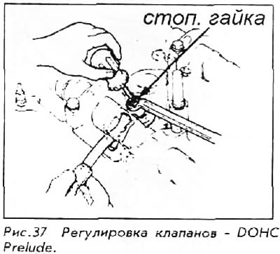
3. Check the clearances on all valves for cylinder No.1 with a feeler gauge between the valve tip and rocker arm contact surface. The probe should pass into the slot with little effort.
4. If the probe goes through without force or cannot be inserted, loosen the lock nut on the adjusting screw,
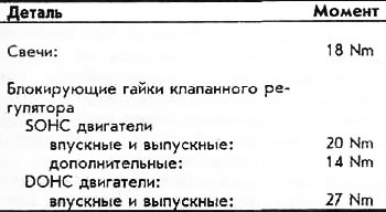
5. Turn the adjusting screw to obtain the required clearance. While holding the screw in this position, tighten the lock nut. The correct tightening torque for the lock nut is: intake and exhaust valves - 20 Nm, auxiliary - 14 Nm. After the locknut is tightened, recheck the clearance and repeat the procedure as needed.
6. Rotate the crankshaft 180°; the camshaft must rotate 90°. One of the grooves in the pulley is now vertical and aligned with the embossed mark on the timing belt cover. UP label (top) is not visible and the distributor rotor points to terminal or wire Number 3.
7. Adjust all valves for Cylinder Number 3 by repeating Steps 3, 4 and 5 as needed.
8. Rotate the crankshaft 180°. Both grooves on the pulley are visible and aligned with the surfaces of the cylinder heads. The distributor rotor points to terminal or wire Number 4.
9. Adjust all valves for Cylinder Number 4 by repeating Steps 3, 4 and 5 as needed.
10. Rotate the crankshaft 180°. One of the grooves on the pulley is again vertical, aligned with the notch on the toothed belt cover. The UP label is visible but not at the top. The distributor rotor points to terminal or wire No.2.
11. Adjust all valves for Cylinder Number 2 by repeating Steps 3, 4 and 5 as needed.
12. Reinstall the valve cover.
1990-1991 Accord
The engines on these vehicles use 2 intake valves and 2 exhaust valves per cylinder.
Valve clearances:
- Intake: 0.24-0.28 mm preferably with 0.26 mm
- Exhaust: 0.28-0.32 mm preferably with 0.30 mm
1. With the ignition off, remove the valve cover.
2. Set the engine to the position corresponding to the TDC of cylinder No.1. UP label (top) on the camshaft pulley should be at the top of the pulley. Two grooves on the back (valvular) side of the pulley should be both visible and aligned with the surface of the cylinder head. The distributor rotor points to terminal or wire No.1.
3. Check clearances on all valves for No. 1 cylinder with a feeler gauge between the valve tip and rocker arm contact surface. The probe should pass into the gap with little effort.
4. If the feeler gauge passes without force or cannot be inserted, loosen the lock nut on the adjusting screw.
5. Turn the adjusting screw to obtain the required clearance. While holding the screw in this position, tighten the lock nut. The correct tightening torque for the lock nut is: intake and exhaust valves - 20 Nm, auxiliary - 14 Nm. After the locknut is tightened, recheck the clearance and repeat the procedure as needed.
6. Rotate the crankshaft 180°; the camshaft must rotate 90°. One of the grooves in the pulley is now vertical and aligned with the embossed mark on the timing belt cover. UP label (top) is not visible and the distributor rotor points to terminal or wire Number 3.
7. Adjust all valves for Cylinder Number 3 by repeating Steps 3, 4 and 5 as needed.
8. Rotate the crankshaft 180°. Both grooves on the pulley are visible and aligned with the surfaces of the cylinder heads. The distributor rotor points to terminal or wire Number 4.
9. Adjust all valves for Cylinder Number 4 by repeating Steps 3, 4 and 5 as needed.
10. Rotate the crankshaft 180°. One of the grooves on the pulley is again vertical, aligned with the notch on the timing belt cover. The UP label is visible but not at the top. The distributor rotor points to terminal or wire No.2.
11. Adjust all valves for Cylinder Number 2 by repeating Steps 3, 4 and 5 as needed.
12. Replace the valve cover.
1988-91 DOHC Prelude
These engines use double overhead camshafts (DOHC) and use 4 valves per cylinder, 2 intake and 2 exhaust. The intake valves are controlled by one cam and the exhaust valves by another. Valve adjustment on these engines is similar to other engines. Each camshaft pulley is labeled UP (top) and grooves; when the engine is turned during the adjustment process, the marks must match both the cylinder head and each other.
Twin cam motors use rocker arms mounted under the camshaft; for this reason, checking clearances with straight thickness gauges can be difficult. Use a set of bent probes if possible. Valve clearances are as follows:
- Inlet: 0.08-0.12mm
- Graduation: 0.16-0.20 mm
1. With the ignition off, remove the cover from the valves.
2. Install piston no. 1 to the position corresponding to TDC. Tags UP (top) on the pulleys must be at the top of the pulley, and the TDC slots on the edge or side of the pulley must be aligned with the surface of the cylinder head. The distributor rotor should point to the No.1 spark plug wire.
3. Check clearances on all valves for Cylinder Number 1 with a feeler gauge. The probe should pass into the gap with little effort.
4. If the feeler gauge passes without force or cannot be inserted, loosen the jam nut on the adjusting screw.
5. Turn the adjusting screw to obtain the required clearance. While holding the screw in this position, tighten the lock nut. The correct tightening torque for the lock nut is: intake and exhaust valves - 27 Nm; After the lock nut is tightened, recheck the clearance and repeat the procedure as needed.
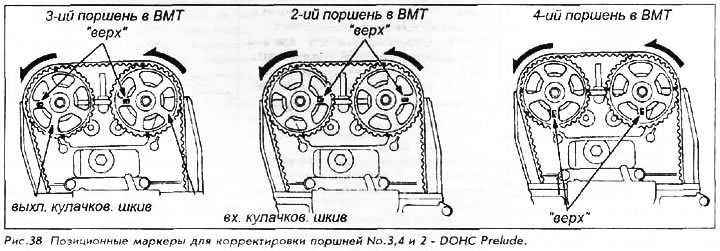
6. Rotate the crankshaft 180°counterclockwise, the camshaft should turn 90°. Up label (top) must be on the side of the exhaust valves. The distributor rotor should point to the No.3 spark plug wire. In this position, the valve clearances on cylinder No.3 can be adjusted. Repeat steps no. 3, 4 and 5 if necessary.
7. Rotate the crankshaft 180°counterclockwise to bring the No.4 piston to TDC. Both labels UP (top) should be down and the distributor rotor should point to the Number 4 wire. The notches on the pulley are aligned with the surface of the cylinder head and with each other. Adjust all valves for Cylinder Number 4 by repeating Steps 3, 4 and 5 as needed.
8. Rotate the crankshaft 180°counterclockwise to bring No.2 cylinder piston to TDC. The UP mark must be on the side of the inlet valves. Distributor rotor points to spark plug wire No. 2. Adjust all valves for Cylinder Number 2 by repeating Steps 3, 4 and 5 as needed,
9. If all valves are adjusted and checked, replace the valve cover. Install the distributor cap. Start the engine and check for oil leaks.
Torque specification