
Note: Before removing the connecting rod and piston assemblies from the engine, it is necessary to remove the cylinder head(s), oil pan and oil pump with oil pickup tube.
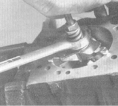
1. Using a special countersink, completely remove traces of stepped wear from the top of the cylinders - follow the manufacturer's instructions included with the countersink. The step is formed at the limit of the piston stroke, approximately 6.4 mm below the top edge of the cylinder due to mechanical wear of metal and carbon formation; its presence can be determined by touch with a fingernail. Attempts to extract the connecting rod and piston groups without removing the stepped wear are fraught with damage to the pistons.
2. Once you have finished preparing the cylinders, turn the engine upside down so that the crankshaft is on top.
3. To gain access to the connecting rods, remove the oil deflector plate.
Note: On 4-cylinder engines, the main bearing caps are connected by a common bridge, which is then attached to the cylinder block. The shaft end play on these engines should be checked before removing this bridge (see Section Removal the crankshaft) (and the oil deflector plate). The axial clearance of the connecting rods on their journals can be determined through the holes in the bridge. To remove the connecting rod assemblies, the bridge must be dismantled.
4. Before removing the connecting rods from the crankshaft, estimate the amount of their axial play on the journals of the latter. Firmly insert the blade(s) of the measuring gauge into the gap between the side wall of the lower head of the connecting rod and the crank cheek, completely removing the play of the connecting rod on the journal of the shaft. The total thickness of the selected blades of the feeler gauge will be equal to the value of the axial play of the connecting rod. Compare the result of the measurement with the requirements of the Specifications. If the value of the axial play exceeds the maximum permissible value, this connecting rod is subject to replacement. The axial play of a new connecting rod, or an old one on a new shaft, may be less than the lower permissible limit, in which case the connecting rod can be machined - consult with specialists at a car service. Check all the remaining connecting rods one by one.
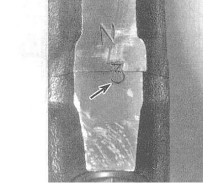
5. Make sure that the connecting rod lower heads and their caps have identification marks indicating that they belong to your cylinder - do not confuse the connecting rod number with the connecting rod bearing size marking,
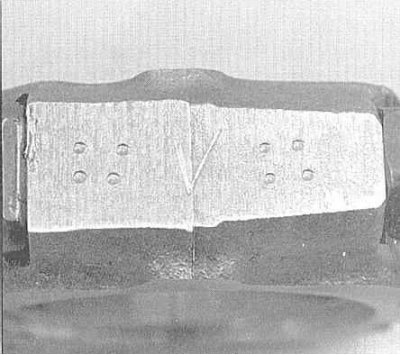
if necessary, make marks yourself using a small center punch.
6. In several steps (1/2 turn per approach), loosen the nuts securing the lower connecting rod head caps enough to allow them to be unscrewed by hand. Remove the first connecting rod cap together with the bearing shell placed in it - try not to drop the latter.
Note: On 4-cylinder engines, the connecting rod and piston assemblies can only be removed after dismantling the main bearing cap bridge (see Section Removal the crankshaft).
7. Remove the bearing shell from the lower connecting rod head, then, using the wooden handle of a hammer against the bearing bed in the lower head, push the connecting rod and piston assembly out through the top of the cylinder through the top of the block. If resistance occurs, immediately stop removing the assembly and check that the stepped wear in the upper part of the cylinder has been completely removed.
8. In a similar manner, remove the remaining connecting rod and piston assemblies from the engine.
Note: The connecting rod to be removed is installed coaxially to its cylinder by turning the crankshaft accordingly - proceed with the extraction only after the connecting rod is positioned strictly parallel to the cylinder axis!
9. To avoid accidental mechanical damage to the bearings and loss of components, reinstall the bearing shells and secure the bearing caps to the lower heads of your connecting rods, hand tightening the nuts.
10. Do not remove the pistons from the connecting rods (for more details, see Section Checking the condition of the connecting rod and piston group components).