
Warning! The models of vehicles covered in this manual are equipped with a supplemental restraint system (SRS). Before performing any work near the air bag unit, steering column or instrument panel, turn off the SRS to avoid injury from accidental deployment (see Chapter On-board electrical equipment). The SRS circuit wiring is easily identified by the yellow color of the insulation.
Removal
1. Remove the center console (see Chapter Body).
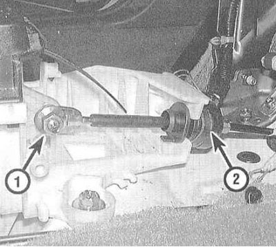
2. Loosen the cable adjuster lock nut.
3. Turn the rubber bushing 1/4 turn counterclockwise and release it from the support bracket together with the cable.
4. Jack up the car and place it on supports.
5. Remove the exhaust pipe with heat shield from under the vehicle (see Chapter Power and exhaust systems).
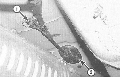
6. Under the vehicle, in the area where the console is located, remove the cable guide bracket and release the rubber bushing of the latter from the bottom panel.
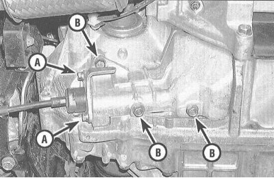
7. Remove the bolts from the shift cable holder.
Note: To avoid damage to the cable connection to the control lever, the holder must be removed before the cover.
8. Loosen the mounting bolts and remove the shift control cable cover.
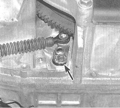
9. Remove the lock bolt and remove the control lever with the shift cable attached to it from the transmission assembly.
Installation
1. Under the vehicle, thread the new cable assembly through the access hole and install the guide bracket in place.
2. Move the gearshift lever (selector) to the "R" position.
3. On the transmission, connect the control lever with the shift cable attached to it to the control rod.
4. Screw in a new lever mounting lock bolt and secure it by bending the lock washer flag.
5. Install the shift control cable holder onto the cover, then install the cover assembly onto the transmission.
6. In the vehicle interior, turn the bushing 1/4 turn clockwise and place the assembly on the support bracket.
7. Turn on the ignition (do not start the engine) and make sure that the reverse gear indicator is on.
8. If the cable is not installed correctly, push it forward until it stops, then pull it back one click to the position corresponding to the reverse gear engagement.
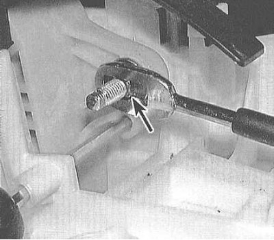
9. Place the cable end onto the shift lever bolt, making sure that the groove is correctly aligned with the rectangular protrusions on the bolt.
10. Move the shift lever through all positions one by one and make sure that the transmission shifts properly.
11. Further installation is carried out in the reverse order of dismantling the corresponding components. If necessary, adjust the shift cable
Adjustment
1. Start the engine, move the selector lever to the "R" position and make sure that the reverse gear is engaged properly. If the gear does not engage, adjust the cable. Turn off the engine.
2. Remove the center console (see Chapter Body).
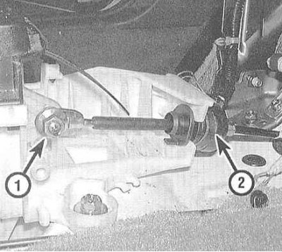
3. Move the selector lever to the "N" position, then loosen the cable adjuster lock nut.
4. Push the cable forward until it stops, then release it - the transmission should shift to the "P" position. Pull the cable back one click so that it locks in the new position, corresponding to the "R" position.
5. Insert a 6.1 mm diameter rod into the special hole in the mounting bracket of the shift lever base - the hole is located on the driver's side of the shift lever housing. After the rod is inserted into the hole in the mounting bracket of the shift lever base, align the shift lever and insert the rod into the hole in its base. The assembly will now be fixed.
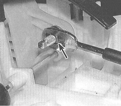
6. Place the cable end onto the lever bolt.
7. Screw on the lock nut and fix the cable in this position.
8. Remove the assembly retaining pin.
9. Start the engine and check that the shift control assembly is functioning properly.
(Based on materials from the website: HONDABOOK)