
Withdrawal
Note. If the wheel hub is not secured with the wheel nuts, start by following the procedure in paragraph 4.
1. Loosen the wheel nuts, jack up the front of the car and place it on jack stands.
2. Give wheel nuts and remove a decorative cap from a disk, remove a wheel.
3. Tap out the hub nut washer with a drift, then reinstall the wheel without the hubcap and lower the vehicle to the ground.
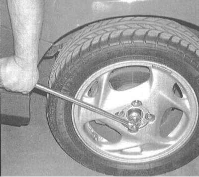
4. Using a socket wrench with a long collar, loosen the hub nut.
5. Loosen the wheel nuts, jack up the front of the vehicle and place it on jack stands. Remove the wheel and give the hub nut.
6. Release the flexible brake hose from the bracket on the steering knuckle assembly. Loosen the brake caliper and tie it with wire to the coil spring. Also remove the caliper anchor bracket and brake disc (see chapter Brake system).
7. Remove the two fixing screws and remove the brake disc from the hub assembly (see chapter Brake system).
8. Remove the ABS wheel sensor (see chapter Brake system).
9. Disconnect the tie rod end from the steering knuckle (see Section Removal and installation of tips of steering draughts).
10. Separate the lower suspension arm from the ball joint at the bottom of the steering knuckle (see Section Removal and installation of the lower control arm of the front suspension).
11. Separate the upper end of the knuckle from the ball joint of the upper suspension arm (see Section Removal and installation of the upper control arm of the front suspension).
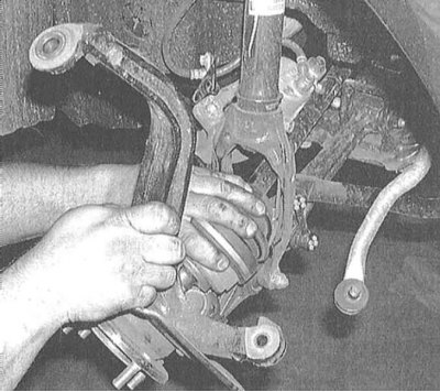
12. Gently pull the knuckle-hub assembly outward, removing it from the drive shaft trunnion. If necessary, tap on the end of the stud with a soft-faced hammer to release the CV joint from the hub. Tie up the driveshaft assembly with wire to prevent damage to the inner CV joint.
13. If there is a need to replace the wheel bearing, take the steering knuckle assembly to a car service workshop.
Installation
1. If the assembly was dismantled, install the hub on the steering knuckle (work must be carried out in a car service workshop).
2. Lightly lubricate the splines of the driveshaft outer pin with special grease. Pass the trunnion through the hole in the hub, while filling the steering knuckle into its regular place.
3. Connect top of knuckle to upper control arm ball joint (see Section Removal and installation of the upper control arm of the front suspension). Tighten the ball stud nut to the required torque and secure it with a new cotter pin.
Note. Tighten the nut to the minimum allowable force, then tighten it until the holes for the cotter pin are aligned.
4. Connect the ball joint at the bottom of the knuckle to the lower suspension arm (see Section Removal and installation of the lower control arm of the front suspension). Tighten the castle nut to the required torque and secure it with a new cotter pin (see remark in previous paragraph).
5. Replace the brake disc by firmly tightening the fixing screws.
6. Install the anchor bracket and caliper by tightening the component fasteners to the required torque (see chapter Brake system). Attach the flexible brake hose to the support bracket on the steering knuckle assembly. Tighten the fixing bolts firmly.
7. Screw the hub nut onto the drive shaft stub and tighten it firmly.
8. Install the wheel (if necessary - disc cap), lower the vehicle to the ground and tighten the wheel nuts to the specified torque (see Specifications to Chapter Settings and ongoing maintenance).
9. Tighten the hub nut to the required torque (see Specifications to Chapter Clutch and drive shafts).