
Common parameters
| Voltage l-probe, V | |
| Open circuit | 0.1÷0.2 |
| Closed circuit | 0.1÷0.9 |
| Crankshaft Position Sensor/TDC Resistance (TFR/TDC), Ohm | 1850÷2450 |
| Piston position sensor resistance (CYP), Ohm | 800÷1500 |
Layout of engine management/emission control systems components in the engine compartment of 4-cylinder models
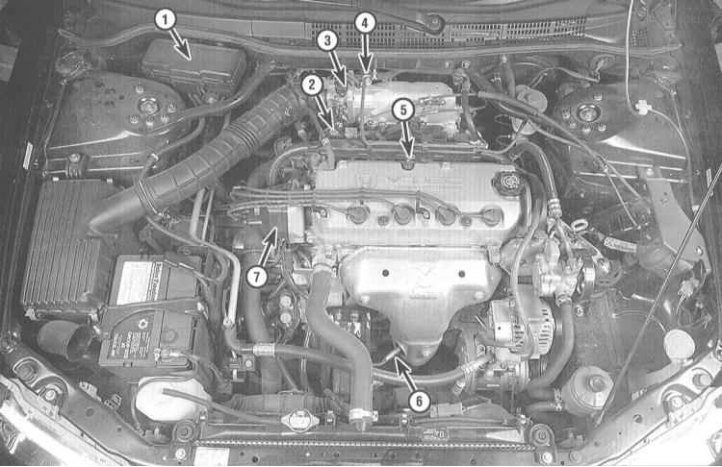
1 - Electrical load control detector (ELD) (as part of a central fuse/relay mounting block); 2 - Exhaust gas recirculation valve (EGR); 3 - Absolute pressure sensor in the pipeline (IDA); 4 - Idle speed stabilization valve (IAC); 5 - Valve of the controlled crankcase ventilation system (PCV); 6 - Oxygen sensor (l-probe); 7 - Piston position sensor (CYP) (as part of the ignition distributor)
Layout of engine management/emission control systems components in the engine compartment of V6 models
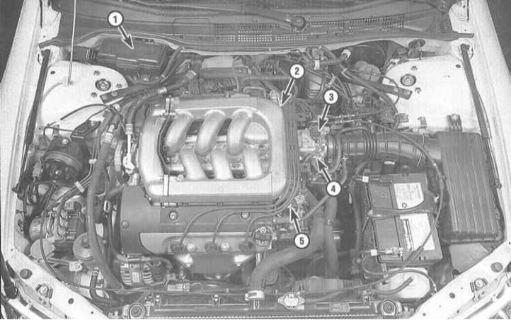
1 - Electrical load control detector (ELD) (under the fuse box); 2 - Valve of the controlled crankcase ventilation system (PCV); 3 - Absolute pressure sensor in the pipeline (IDA); 4 - Throttle position sensor (TPS); 5 - Exhaust gas recirculation valve (EGR)
In order to reduce the level of emissions into the atmosphere of toxic components that enter the composition of the exhaust gases of the engine as a result of evaporation and incomplete combustion of fuel, as well as to maintain engine efficiency and reduce fuel consumption, the vehicles covered in this Guide are equipped with a number of special systems that can be would unite under the general name of engine management systems and reduce the toxicity of exhaust gases.
Systems related to engine management and emission control include the following:
- a) On-Board Diagnostic System (OBD);
- b) Electronic engine management system (PGM-FI);
- c) Electrical load monitoring detector (ELD);
- d) Exhaust gas recirculation system (EGR);
- e) Evaporative Emission System (EVAP);
- f) Controlled crankcase ventilation system (PCV);
- g) catalytic converter.
The functioning of all these systems, one way or another, directly or indirectly, is related to the management of the reduction of exhaust gas toxicity.
The following Sections provide general descriptions of how each system operates, as well as procedures for diagnostic checks and remedial repairs (if it is possible) components of systems, the performance of which lies within the qualifications of the average amateur mechanic.
Before coming to the conclusion that any of the emission control systems have failed, carefully check the power and ignition systems for proper functioning (see chapters Power and exhaust systems and Engine electrical equipment). Diagnostics of some of the components of toxicity reduction systems requires the use of special, difficult-to-use equipment and a certain qualification of the performer, and therefore, it would be reasonable to entrust its implementation to professional mechanics of a specialized service station.
The foregoing does not mean that the maintenance and repair of components of toxicity reduction systems in practice seem difficult. Do not forget that one of the most common causes of failures is an elementary violation of the quality of vacuum or electrical connections, and therefore, first of all, you should always check the condition of the fittings and electrical connectors. The car owner can independently and quite simply carry out a number of checks, as well as perform many routine maintenance procedures for most system components at home, using the usual set of tuning and locksmith tools. Note: Be aware of additional federal warranties that apply to emission control and engine management components. Before starting any repair procedures for components and parts of these systems, consult the terms of compliance with these obligations at the representative office of Honda.
Try to observe all the precautions specified in the following Sections when performing maintenance of the electronic components of the systems in question. It should be noted that the illustrative material may not always exactly match the actual placement of components on the vehicle. Such inconsistencies are associated with the ongoing process of modification within the framework of the typical design of each model.
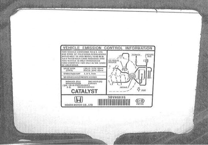
An information label of exhaust gas toxicity reduction systems is fixed in the engine compartment of the car (VECI). The label contains the necessary information on the settings and checks of controlled systems, taking into account all modifications made to a particular vehicle, as well as a diagram of the laying of vacuum hoses with the identification of various components. Read the VECI data carefully before servicing the emission control and engine management systems.