
HondaBook.ru
Auto companies Volkswagen Auto companies Ford Auto companies Lada Auto companies Skoda Auto companies BMW Auto companies Mazda Auto companies Peugeot
English Русский
Български
Беларускі
Український
Српски
Hrvatski
Română
Polski
Slovenský
Magyar
Bookmark Contacts Sitemap   


Accord Civic Fit / Jazz CR-V HR-V Others Articles
Accord 3 (1985-1989) Accord 6 (1997-2002)

Checking the breaker module input (Honda Accord 3)

  • Main
  • Honda Accord
  • 3 (1985-1989)
  • Power unit
  • Engine adjustment
  • Checking the breaker module input
0

Checking the breaker module input on ACCORD 1990-91


1. Remove the distributor cap, rotor and screen.

2. Label and disconnect the 4 wires from the breaker module.

3. Turn the ignition ON. Use a voltmeter to check for voltage between the black/yellow wire and ground. There should be voltage. If there is no voltage, check the integrity of the black/yellow wire between the breaker module and the ignition switch.

4. Check the voltage between the white/blue wire and ground; Voltage should be present when ignition is on. If not, check the white/blue wire from the breaker module to the coil. The ignition coil itself should also be checked.
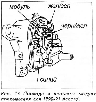
4. Check the voltage between the white/blue wire…


5. Turn off the ignition (OFF position). Check the integrity of the yellow/green wire between the module and the ECU.

6. Check the blue wire for continuity between the tachometer and the breaker module.

7. If all tests are normal, then the module needs to be replaced.

Checking the input of the breaker module for carburetor PRELUDE 1990 with distributor of the company TOYO DENSO
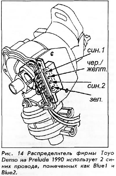


Checking the input of the breaker module for…


1. Remove the distributor cap, rotor and screen. Remove the bolts holding the distributor and remove the distributor for access. Leave the wiring harness connected to the distributor.


2. Remove the breaker module.

3. Turn on the ignition and check the voltage between the terminal of the blue wire (1) (the outermost blue wire) and ground; there should be tension.

4. Check the voltage between the black/yellow terminal and ground (earth); there should be tension.

5. If there is no voltage in any of the tests, turn the ignition off. Check the blue wire (1) between the breaker module and the ignition coil; check the black/yellow wire between the breaker module, ignition key and coil. Check the coil as well.

6. If all tests are OK and the problem still exists, the breaker module needs to be replaced.

7. Replace the screen, rotor and cover. Install the distributor.

Checking the input of the breaker module for carburetor PRELUDE 1990 with a distributor from HITACHI


1. Remove the distributor cap.

2. Label and disconnect the wires from the breaker module.

3. Turn on the ignition. Check the voltage between the blue wire and ground. There should be voltage.

4. Check the voltage between the black/yellow wire and ground. There should be voltage.

5. If there is no voltage in any test, turn off the ignition. Check the continuity of the blue wire between the ignition coil and the breaker module. Check the continuity of the black/yellow wire between the ignition key, coil and breaker module.

6. Using an ohmmeter (Rx100 scale), check the continuity at the breaker module terminals. Continuity should only exist in one direction.

7. If all tests are normal and the problem still exists, the breaker module needs to be replaced.


8. Install the distributor cap.

Checking the breaker module input for PrElUdE 1990-91 fuel injected vehicles


1. The breaker module is located on the right front of the shock absorber. With the ignition off, disconnect the breaker module connector.

2. Turn the ignition to the ON position. Check the voltage between the blue wire and ground. There should be voltage.

3. Check the voltage between the black/yellow wire and ground. There should be voltage.

4. If there is no voltage in any test, turn the ignition off. Check continuity of the blue wire between the ignition coil and the breaker module. Check continuity of the black/yellow wire between the ignition key, coil and breaker module.

5. Check the continuity of the white wire between the ECU and the interrupter module connector.
This article is available at: russian, bulgarian, belarusian, ukrainian, serbian, croatian, romanian, polish, slovak, hungarian
This information has been verified: Yaroslav Shiryaev
Share with friends:
◀ Previous
Accord 3: Engine adjustment
Next ▶

Checking the breaker module
Checking and adjusting the magnetic resistance gap
Electronic ignition — description and diagnostics
Frequency of ignition
Spark plug connection wires
Checking the spark
Ignition Coil Test
Replacement of ignition system parts
Ignition timing — checking and adjustment
Valve clearance — adjustment
See also other articles from Honda manuals:
Checking the Ignition Control Module (ICM) Input Signal Honda Civic 5 and 6 (1991-2000)
Checking tire pressure and condition Honda Fit 1 (2001-2008)
Electronic Ignition Module — Checking and Replacing Honda CR-V 1 (1995-2001, petrol)
Checking the starter brushes Honda HR-V 1 (1998-2006, petrol)
Door locks with electric drives — checking the input signals of the… Honda Avancier 1 (1999-2003, petrol)
Link in different formats to this article
Comments and feedback from visitors
No comments yet


How much will 39 + 39 ?


Accord 6 (1997-2002) 
  • General information
  • Introduction to the guide
  • User manual
  • Maintenance
  • Power unit
  • Four-cylinder engines
  • Six-cylinder engines
  • Engine overhaul
  • Cooling system
  • Heater and air conditioner
  • Power and exhaust systems
  • Engine electrical equipment
  • Engine management
  • Transmission
  • Mechanical gearbox
  • Automatic gearbox
  • Clutch and drive shafts
  • Chassis and running gear
  • Brake system
  • Car suspension
  • Steering
  • Body and interior
  • Exterior (external elements)
  • Interior (internal elements)
  • Electrical equipment
  • Equipment and devices
  • Electrical circuits
Accord 3 (1985-1989) 
  • General information
  • Maintenance
  • Power unit
  • Engine adjustment
  • Engine repair
  • Engine electrics
  • Emission management
  • Engine management (carburetor)
  • Electronic injection
  • Programmable injection
  • Schematic of emission system
  • Fuel system
  • Feedback management
  • Transmission
  • Manual gearbox
  • Automatic gearbox
  • Clutch
  • Chassis and running gear
  • Front suspension
  • Rear suspension
  • Steering
  • Brake system
  • Electrical equipment
  • Ventilation and heating
  • Air conditioner
  • Cruise control system
  • Equipment and devices
HondaBook.ru © 2018–2026 • Mobile version • Sitemap: EN BG BY UA RS HR RO PL SK HU • Feedback • Driver Information • Search system • Bookmark
Accord 3 (1985-1989) • Accord 6 (1997-2002) • Civic 3 and 4 (1983-1991) • Civic 5 and 6 (1991-2000) • Civic 6 (1995-2000) • Civic 7 (2000-2005) • Civic 8 (2005-2011) • Fit 1 (2001-2008) • CR-V 1 (1995-2001) • CR-V 2 (2002-2006) • HR-V 1 (1998-2006) • Avancier 1 (1999-2003) •
 
This website uses cookies to ensure proper functioning. By clicking "OK," you agree.