
CAUTION: Honda's anti-lock braking system contains extremely high pressure brake fluid inside the pump, accumulator and modulator. Do not disconnect or loosen lines, hoses, joints or components without properly depressurizing the system. To do this, use ONLY tool 07HAA-SG00101 or equivalent. Incorrect actions can result in serious injury!
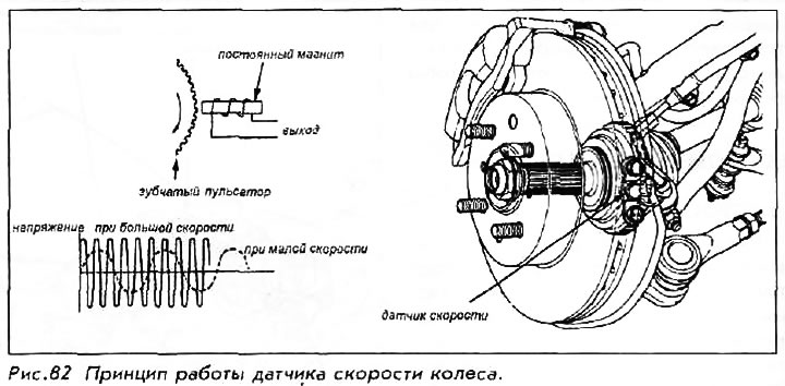
Wheel speed sensors
Information about the speed of each wheel is transmitted to the control unit through wheel speed sensors. A small sensor unit is mounted above a cogwheel that rotates with the axle or road wheel.
Wheel speed sensors generate an alternating voltage as the gear passes. The frequency of this voltage is used by the control unit to calculate the wheel speed. By comparing the speeds of the wheels during braking, the control unit determines the impending wheel lock.
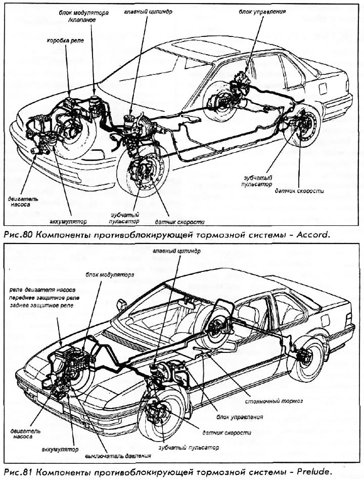
Control block
The control unit performs the main function of controlling the solenoid valves of the modulator, processing electrical signals from sensors installed on the wheels of the vehicle. Additional functions of the control unit include self-diagnostics, pump motor control and system shutdown.
In addition, the ABS control unit receives signals from the parking brake signal switch, charging system, ignition key, brake light switch, pump motor relay and protection relay. Each signal is used to "help" control unit in analyzing the operation of the system. Damage to any of the relevant components may cause the ABS to disengage.
Hydraulic Modulator
The modulator contains solenoid valves for each brake circuit. The control unit controls each electromagnet individually (one for each front wheel and one for both rear wheels), based on the signals from the wheel speed sensors.
The modulator receives brake fluid from the accumulator at extremely high pressure. This liquid passes into the system through the solenoid valve and increases the pressure in the pipeline if necessary. Separate channels allow fluid to flow back if the pressure needs to be relieved. The assembly contains 4 modulators or pistons with springs, which serve to absorb high pressure impulses inside the system.
Under certain conditions, the pressure in the system can exceed 20,000 kPa. For this reason, extreme care is required when handling the modulator or associated piping and fittings. Always properly depressurize the system before doing any work.
Accumulator and pressure sensor
The accumulator stores the high pressure brake fluid from the pump, making it available to the system when needed. When the control unit determines the need for anti-blocking, fluid under pressure passes into the control chamber of the modulator through the inlet of the solenoid valve. The ball battery is mounted separately under the modulator block in the right front engine bay on both the Accord and Prelude.
A pressure sensor installed with the accumulator monitors the pressure inside the accumulator and transmits a signal to the control unit. If the pressure drops below the minimum requirements (usually due to anti-blocking action), a signal from the control unit is sent to the pump, which restores pressure. Usually the necessary pressure is restored within 3-5 seconds. If this does not happen within 120 seconds after the start of the pump, the control unit disables the ABS and turns on a warning lamp on the dashboard.
Pump motor (Power block)
The pump and its motor are not part of the modulator; they are installed separately and are located next to the battery. The power unit consists of a motor and a pump. The unit creates high pressure brake fluid and sends it to the battery for storage. The control unit starts the pump every time the car starts and if the speed becomes more than 10 km / h. The pump maintains the accumulator pressure at a maximum of 230 kg/cm2. The 200 watt pump motor is equipped with a 40 amp fuse located in the under hood fuse box on the Prelude or in the ABS fuse box in the engine bay on the Accord.
Pump motor relay and protection
The three system relays are controlled by the control unit. The pump motor relay is located in the under hood fuse box on the Prelude or in the ABS fuse box in the engine bay on the Accord. On the Accord, the front and rear protection turnips are located at the rear right of the trunk, next to the control unit. The safety relay on the Prelude is located under the hood in the relay box.
Safety relays regulate the power supply to the output control valves inside the modulator. If the control unit detects damage inside the ABS, then the relays are de-energized. The valves go to the fully open state, do not provide any pressure control.
Warning lamp
An amber light on the instrument panel alerts the driver that ABS damage has been detected and that the anti-lock function has been disabled. The ANTILOCK warning lamp comes on in the following situations:
- After the machine is started for the first time, the pump indicates that the self-diagnosis system is operational and that the warning lamp is working. The signal should turn off after a few seconds.
- When the parking brake is applied for more than 30 seconds while the vehicle is moving.
- When either rear wheel locks up for more than a certain amount of time.
- In the absence of any signal from the wheel speed sensors.
- If the operating time of any solenoid valve exceeds certain limits or the control unit detects an open in the solenoid circuit.
- If the control unit does not detect any action of the electromagnet in response to its signals.
- If the pump run time exceeds 120 seconds.
Safety measures during work
If the car is equipped with the SRS security system (air bag), always properly disable the system before working on the anti-lock system. Connectors and electrical wiring of the airbag - yellow; do not use electrical test equipment to test these circuits.
Do not use rubber hoses or other parts not specifically specified for the anti-lock system. When using repair kits, replace all parts included in the kit. Partial or incorrect repairs may result in functional problems and require the replacement of other components.
Lubricate the rubber parts with clean, fresh brake fluid to make assembly easier. Do not use oily workshop air to clean parts; rubber components may be damaged.
Use brake fluid only from an unopened container. The use of contaminated brake fluid may reduce system performance and/or durability. Always use fresh brake fluid during bleeding or pressure relief procedures.
Maintain cleanliness in the repair area. Carry out repairs only after the components have been thoroughly cleaned; Use only denatured alcohol for cleaning. Do not allow the components of the anti-lock system to come into contact with substances containing mineral oils or oily products; this also applies to used rags.
The control unit is a microprocessor, similar to other computing units in a car. Before disconnecting or connecting connectors, make sure the ignition key is in the off position (OFF). Avoid discharging static electricity near the control box.
Never disconnect or connect electrical connectors with the ignition key in the on position (ON), unless any verification procedure specifically instructs to do so.
Avoid touching the connector pins with your fingers.
Keep new components and assemblies in their original packaging until you are ready to install them.
To avoid discharging static electricity, always touch "masses" vehicle after contact with seats or vinyl floor mats.
If welding work is to be carried out on the vehicle, first disconnect the control unit.
Make sure that the welding cables do not intersect with the vehicle's electrical wiring.
If the vehicle is to be dried after painting, disconnect and remove the control unit from the vehicle first.