
- After removal, replace the self-locking nuts.
- The vehicle must be lowered to the ground before tightening the bolts or nuts on the rubber mounts or bushings.
- Before tightening the upper and lower stabilizer link mounting nuts, adjust the link position with the suspension loaded with the weight of the vehicle.
- After installing the suspension arm, check the front wheel alignment angles and adjust if necessary (see above).
- When replacing the stabilizer bar, separate the left ball joint and steering knuckle.
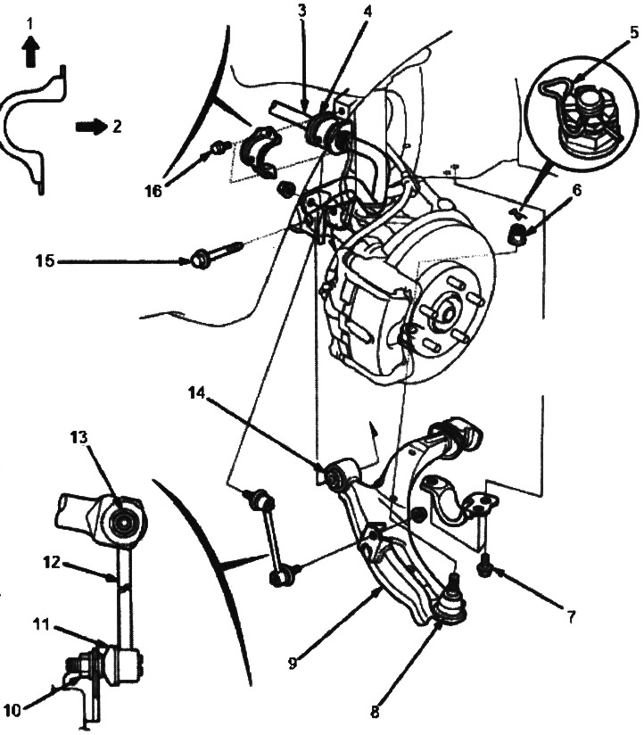
1. TOP
2. BODY
3. STABILIZER BAR. Check for bending and damage.
4. STABILIZER BUSHING. Check for bending and damage.
5. CLAMP Replace. Make sure the clamp fits securely on the nut as shown.
6. CASTLE NUT, 12x1.25 mm, 49-59 Nm (5.0-6.0 kgf/m)
7. BOLT WITH SHELL, 12x1.25 mm, 88 Nm (9.0 kgf/m)
8. BALL JOINT BOOT. Check for wear and damage. Replace boot (see below).
9. LOWER ARM. Check for damage.
10. SELF-LOCKING NUT, 10x1.25 mm, 29 Nm (3.0 kgf/m). Lock the ball joint pin with an Allen key and tighten the self-locking nut.
11. COVER. Check for wear and damage.
12. STABILIZER LINK. Check for bending and damage.
13. SELF-LOCKING NUT, 10x1.25 mm, 38 Nm (3.9 kgf/m). Secure the ball joint pin with an Allen key and tighten the self-locking nut.
14. LOWER ARM RUBBER BUSHING. Check for wear and damage.
15. BOLT WITH SHELL, 14x1.5 mm, 103 Nm (10.5 kgf/m)
16. BOLT WITH SHELL, 8x1.25 mm, 22 Nm (2.2 kgf/m)