


Contents: Inner CV joint ⇊ Outer CV joint ⇊
Note. If defects in the protective cover are detected, the condition of the corresponding CV joint should be carefully examined. Often, fully restored drive shaft assemblies can be purchased on an exchange basis, which greatly simplifies the situation and reduces time costs. Before starting to dismantle the components, conduct marketing, finding out the prices of the necessary spare parts. Compare them with the costs of purchasing restored assemblies.
In car accessory stores, you can find split protective covers for CV joints. Installing such covers does not require dismantling the shaft from the car, which is, in principle, very convenient. However, the authors of this Guide still recommend removing the shafts to check the condition of the CV joints and fill them with fresh grease.
1. Remove the drive shaft (see Section Removal and installation drive shafts).
2. Clamp the removed shaft in a vice with soft jaws.
Inner CV joint
Disassembly
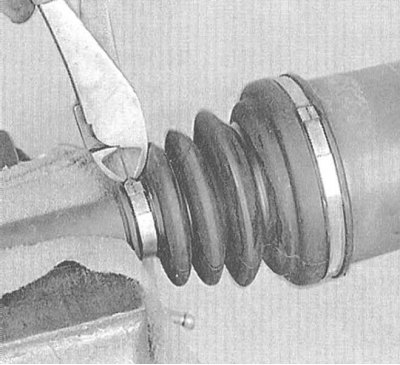
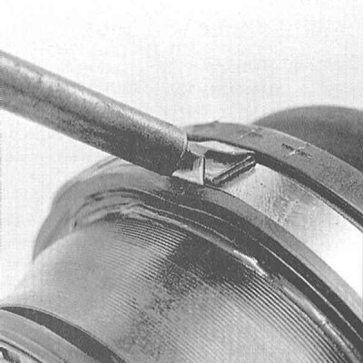
1. Assess the external condition of the CV joint protective cover; if there is the slightest doubt, the cover should be replaced. Cut off the bandage tapes securing the cover and move the latter from the joint to the center of the shaft.
 |
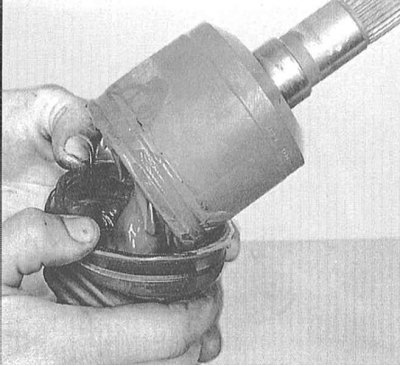 |
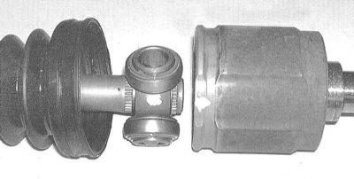
2. After thoroughly wiping the components, mark the position of the tripod bearing assembly with paint or a scriber. Remove the outer race from the bearing.
3. Remove the snap ring from the outer shaft journal.
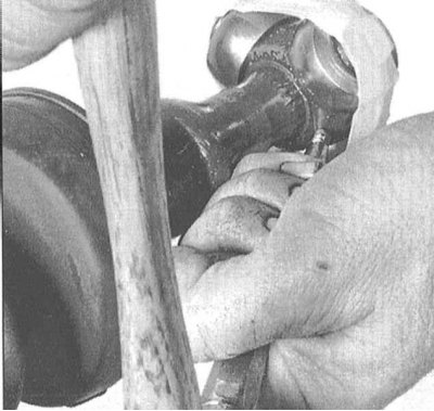
4. Secure the bearing rollers by wrapping them with tape, then knock the tripod assembly off the shaft using a hammer and brass drift.
5. Remove the retaining ring and remove the old protective boot from the drive shaft.
Examination
1. Carefully remove traces of grease from the outer race of the joint and the cavities of the tripod bearing. In order not to mix them up, remove each section of the tripod assembly one by one and wash the needle bearing rollers with solvent.
2. Check the rollers, bearings, supporting part of the tripod assembly and the outer race of the joint for signs of excessive wear of cavities, scoring, cracks and other mechanical damage. Replace the CV joint if necessary.
Assembly
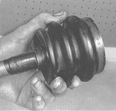
1. Wrap the splines of the drive shaft journal with tape to protect the new CV joint boot from cuts.
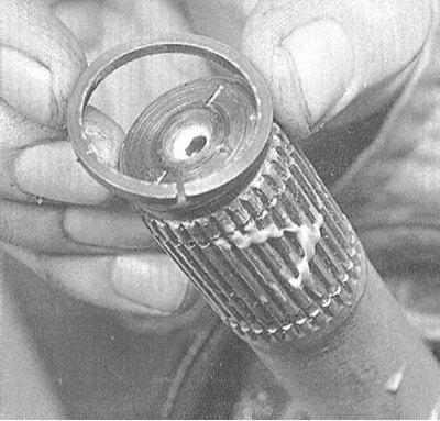
2. Place the cover on the shaft, remove the tape and install the internal retaining ring.
3. Place the tripod assembly on the shaft.
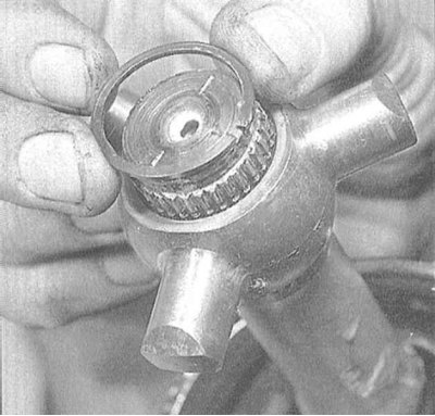
4. Secure the tripod assembly with the outer retaining ring.
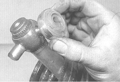
5. Lubricate the inside of the needle roller bearings with a special thick grease to temporarily fix them on the supporting elements of the tripod assembly. Make sure that each roller is installed strictly in its original place.
Note: If the rollers are equipped with a rectangular flat, make sure that they are installed with the flat facing the shaft.
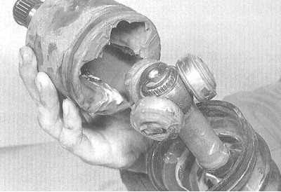
6. Half-fill the outer race of the joint with the grease supplied with the new boot. Fill the boot with the remaining grease. Install the outer race on the shaft. Make sure that the marks for the relative positions of the race and the tripod bearing, made during dismantling, are correctly aligned.
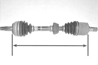
7. Insert the lips of the boot into the grooves on the outer race of the joint and the shaft body, then adjust the length of the shaft assembly according to the requirements of the Specifications.
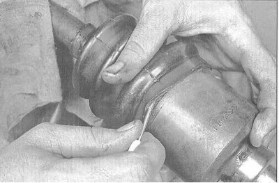
8. After setting the shaft length, release the air from under the cover by prying its outer (larger diameter) edge with a blunt screwdriver. Try not to damage the cover.
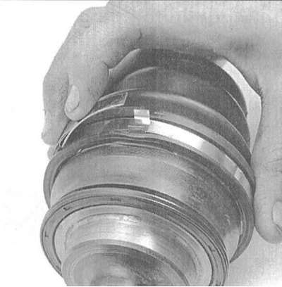
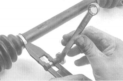
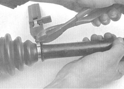
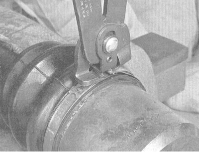
9. Secure the cover with new bandage straps/clamps.
 |
 |
 |
 |
10. Install the shaft assembly to the vehicle (see Section Removal and installation drive shafts).
Outer CV joint
Disassembly
1. Acting in accordance with the instructions set out in paragraphs c 1- 5, remove the inner CV joint from the drive shaft and disassemble it.
2. If the shaft is equipped with a dynamic load damper, mark with paint the position of the outer edge of the damper assembly relative to the shaft, then cut the clamp and remove the damper.
Note: When replacing components, ensure that the distance between the inner CV joint boot and the damper is maintained (see Specifications).
3. Cut off the bandage tapes and remove the CV joint protective cover from the shaft.
Note: The outer CV joint cannot be disassembled or removed from the shaft.
Examination
1. Thoroughly wash the inner and outer CV joints with solvent, then dry them using compressed air.
Caution! When using compressed air, do not forget to wear safety glasses!
Since the outer CV joint cannot be disassembled, removing traces of old grease and solvent from it is associated with certain difficulties, but must be done in the most thorough manner.
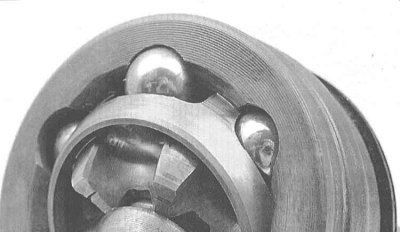
2. Rotate the hinge housing at different angles and carefully examine the condition of the balls, races and bearing separator. If defects are found, replace the shaft assembly.
Assembly
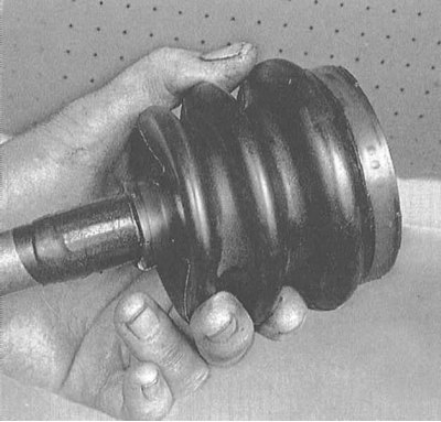
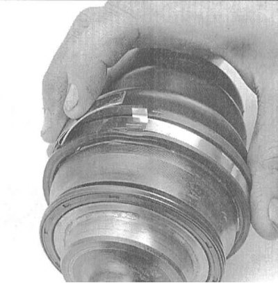
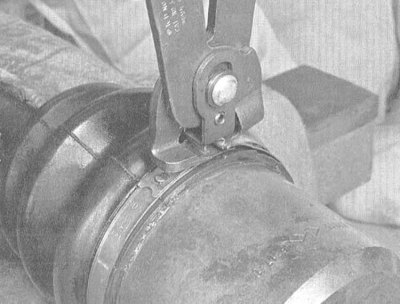
1. Wrap the splines of the drive shaft journal with tape to protect the new CV joint boot from cuts. Put the boot on the shaft, remove the tape, then fill the boot with the grease included in the repair kit. Bring the boot into working position and secure it with new bandage tapes.
 |
 |
2. If the vehicle is equipped accordingly, install the dynamic load damper on the shaft. Make sure that the outer edge of the damper is positioned in accordance with the marks made during dismantling.
Note: When replacing the shaft assembly with the outer joint, the damper is aligned relative to the protective boot of the outer CV joint in accordance with the results of the measurement made in paragraph 20.
3. Clean and assemble the inner CV joint assembly (see paragraphs 8 through 17). Install the drive shaft assembly to the vehicle (see Section Removal and installation drive shafts).
(Original published on this resource: hondabook.ru)