
Warning! The car models covered in this manual are equipped with an additional security system (SRS). Before doing any work near the airbag unit, steering column or instrument panel, turn off the SRS to avoid injury if it is accidentally deployed (see chapter Onboard electrical equipment). SRS circuit wiring is easily identified by the yellow color of the insulation.
Disconnect the negative cable from the battery.
Attention! If the stereo system installed in the car is equipped with a security code, before disconnecting the battery, make sure that you have the correct combination to activate the audio system!
Instrument panel trim
1. If the vehicle is equipped accordingly, lower the steering column to the lower position.
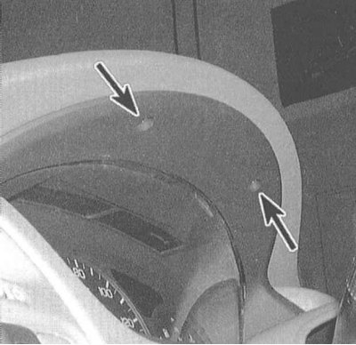
2. Remove the two fixing screws at the top of the cladding.
3. Gently prying with a screwdriver, release the latches and separate the lower part of the shield lining from the instrument panel. In order not to scratch the surface of the panel, cover the tip of the screwdriver with tape.
4. Installation is carried out in the reverse order. Track reliability of a latching of clamps.
Knee support
1. Remove the front cover of the center console (see Section Removal and installation of the center console).
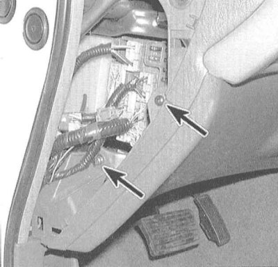
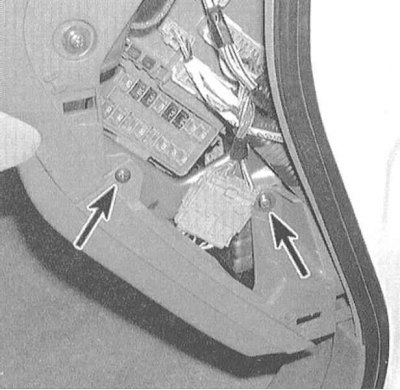
2. Prying off, remove the plastic cover of the fuse mounting block on the left under the instrument panel. Remove the two fixing screws located under the cover.
3. Remove the upper right knee support screw, then pry up the assembly by releasing the retaining clips.
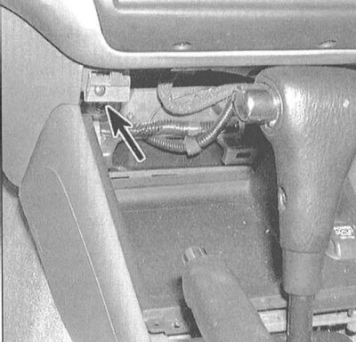
4. If it is necessary to provide access to the components located under the dashboard, turn out bolts of fastening of a rib of rigidity of assembly of a knee emphasis. Pull the bottom edge of the rib and remove the assembly from the vehicle interior.
5. Installation is carried out in the reverse order.
Central section
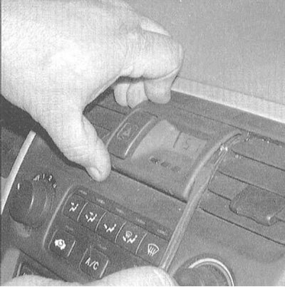
1. Using a tape-wrapped screwdriver, pry off the trim of the panel clock assembly.
2. Having released facing, disunite sockets of an electroconducting of hours and the alarm switch.
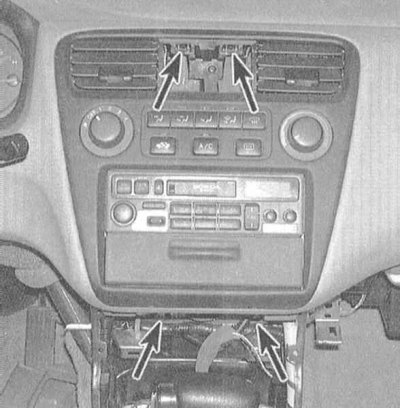
3. Turn out screws of fastening of the central section of the panel of devices. One of the screws is located in the upper recess for fitting the watch face, two - from the bottom. The rest of the panel is fixed with plastic clips.
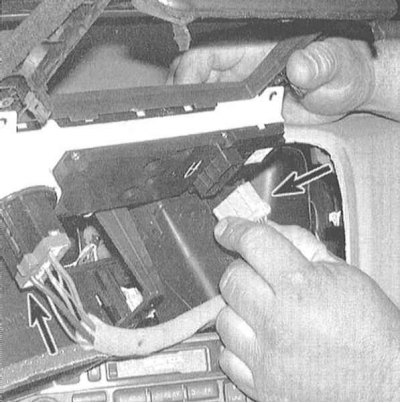
4. The control panel for the operation of the heater / air conditioner is attached to the instrument panel with screws screwed in from the back. Release the panel from its seat, disconnect the electrical wiring and remove the assembly.
5. Installation is carried out in the reverse order.
Right lower section of the instrument panel, glove box
1. Removing the lower side cover from the passenger side of the instrument panel is similar to removing the knee brace assembly. Pry off the instrument panel end cover (to gain access, open the passenger door) and remove the two fixing screws. The third screw is located in the upper left corner of the panel.
2. Prying off the lower edge of the panel, one by one release the latches of its fastening. Remove the panel.
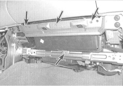
3. Turn out screws of fastening of the bottom edge of assembly of a ware box.
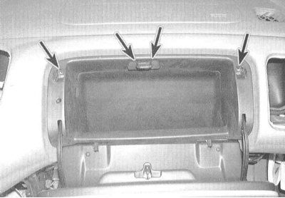
4. Open the drawer door, use a screwdriver to remove the plastic plugs and unscrew the screws securing the top edge of the assembly.
5. Press the hinges of the glove box door towards each other to release the mounting clips, then pull the assembly down and out, releasing it from the panel.
Note. Having released assembly of a ware box from the panel, disunite a socket of electroconducting of its illumination.
6. Installation is carried out in the reverse order.