
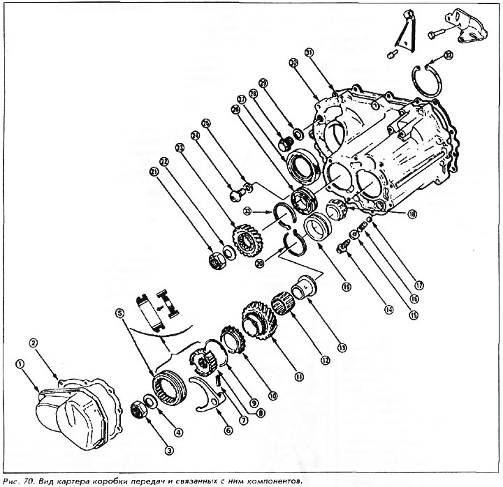
1. End cap
2. Gasket
3. Locknut
4. Spring washer
5. Synchronizer sleeve 5th gear
6. 5th shift fork
7. Cylindrical pin (finger)
8. Synchronizer hub 5th gear
9. Synchronizer spring
10. Synchronizer ring 5th gear
11. Gear wheel of the 5th gear of the input shaft
12. Needle bearing
13. Cuff-gasket
14. Locking screw
15. Washer
16. Spring
17. Retainer ball
18. Roller bearing
19. Bearing outer ring
20. Retaining ring
21. Locknut
22. Spring washer
23. Pinion gear battle transmission output shaft
24. Drain plug
25. Washer
26. Ball bearing
27. Oil seal
28. Filler plug
29. Washer
30. Carter boxes
31. Gasket
32. Retaining ring
33. Retaining ring
34. Oil seal
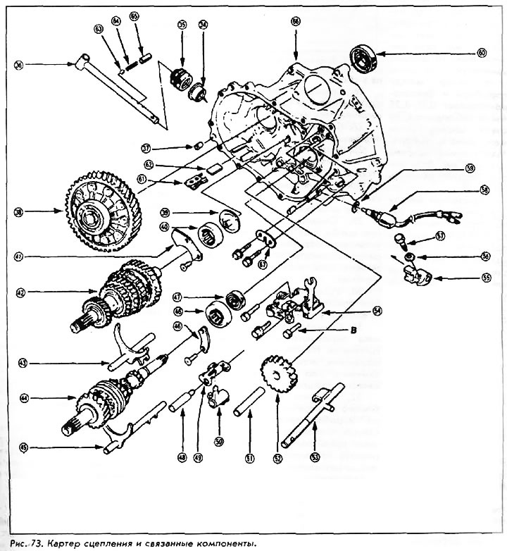
35. Case (anther)
36. Shift rod
37. Locating pin
38. Differential assembly
39. Oil deflector
40. Output shaft bearing
41. Bearing lock plate
42. Output shaft
43. Shaft switching 1st / 2nd gear
44. Primary shaft assembly
45. 3rd/4th shift shaft
46. Input shaft bearing and lock plate
47. Oil seal
48. Shift guide shaft
49. Retainer
50. Shift rod guide
51. Reverse intermediate gear shaft
52. Intermediate reverse gear
53. 5th/reverse shift shaft
54. Shift lever holder
55. Gear shift rod guide
56. Washer
57. Bolt
58. Reversing light switch
59. Washer
60. Oil seal
61. Magnet holder
62. Magnet
63. Retainer ball
64. Spring
65. Spring bushing
66. Clutch housing
67. Breather chamber plate
1. Remove the transmission end cover.
2. Install the input shaft holder. This tool is part number 07923-6890101. Shift gear into reverse.
3. Loosen the locknuts on the input shaft and output shaft. The input shaft locknut has a left-hand thread.
4. Pull out the spring clip from the 5th shift fork shaft.
5. Remove the complete input shaft elements - 5th gear, shift fork, synchronizer clutch, synchronizer hub and spring ring.
6. Remove the gear wheel of the 5th gear of the secondary shaft.
7. Remove the 3 set screws, washers, springs, and detent balls.
8. Remove the switch of a lantern of a backing.
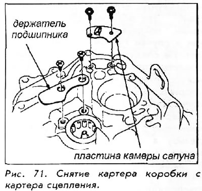
9. Remove 13 crankcase bolts.
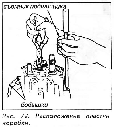
10. Loosen the crankcase by tapping on the edge with a light hammer or wooden mallet. To separate the gearbox housing from the clutch housing, remove the bearing puller attachment 079366340000 or equivalent and screw it into the hole in the gearbox housing. Once the circlip is released, use the bearing puller like a hammer.
11. Before removing the reverse shift fork, measure the clearance between it and the 5th gear/reverse shift shaft stop pin. The tolerance of this gap is 0.05-0.5 mm. If the tolerance is not maintained, measure the width of the groove in the reverse shift fork. The maximum width must be 7.25 mm. If it is not observed, then the plug should be replaced.
12. Measure the clearance between the reverse idle gear and shift fork. The tolerance is 0.20-1.7 mm. If the tolerance is not maintained, then the fork should be removed and the distance between the pawls of the fork should be measured, the tolerance of which is 11.8-12.1 mm. If the tolerance is not maintained, the plug must be replaced.
13. Remove the reverse shift fork/shift lever arm holder if not already removed.
14. Switch the transmission to neutral. Remove the input shaft bearing retainer plate.
15. Pull out the shift guide shaft.
16. Remove the idler shaft and reverse idler gear.
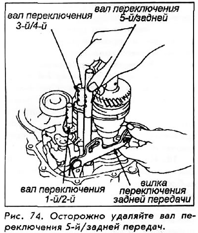
17. Pull up the 3rd/4th and 1st/2nd shift shafts to shift into 4th and 2nd gears. Remove the 5th/Reverse shift shaft by pulling it up while lifting the reverse shift fork.
18. Measure the clearance between the bushing and the gasket on the select lever shaft. The tolerance is 0.01-0.2 mm. If the tolerance is not observed, then the holder of the shift lever arm should be disassembled and the gasket replaced. A set of shims is available from 0.8 to 1.6 mm in 0.2 mm increments.
19. Measure a backlash between a shoulder of the lever of switching and directing rod of switching. The tolerance is 0.10-0.60 mm. If the tolerance is not met, then measure the width of the groove in the guide. The maximum allowed width is 8.00 mm. If the width is greater than specified, the guide should be replaced.
20. Measure a backlash between a shoulder of the lever of a choice and a clamp. The tolerance is 0.70-0.25 mm. If the tolerance is not observed, then the width of the gap between the fingers of the selector lever should be measured. The maximum allowable slot width is 10.15 mm. If the width is greater, then the lever should be replaced.
21. Measure the distance between the shift lever arm and shift guide rod. The tolerance is 0.05-0.80 mm. If the tolerance is not met, then measure the width of the groove in the guide rod. The maximum allowable width is 12.0 mm. If the width is greater than specified, then the tie rod guide must be replaced. If the width is correct, then measure the width of the key on the shoulder of the select lever. The minimum allowed width is 11.9 mm. If the width is less, then the lever should be replaced.
22. Tilt the retainer and tie rod guide to the side and pull them out.
23. Remove output shaft and input shaft assembly with 1st/2nd and 3rd/4th shift shafts. Inspect the shafts and especially the gripping grooves for damage.
24. Remove draft of a gear change and a cover. Inspect the rod for damage and the cover for tears.
25. Remove the differential assembly.
26. Remove the circlip in the gearbox housing. Remove the axle seals from both crankcases.
27. Remove the bearing retainer plate.
28. Insert the bearing puller, or equivalent, with prefix 07936-6890101 or 07736-A01000A into the output shaft bearing. Remove the bearing with a hammer.
29. Remove the oil slinger, wash it thoroughly and reinstall. Reinstall the output shaft needle bearing if it will not be replaced.
30. Reinstall the bearing retainer plate. Tighten the screws and sink the screw heads.
31. Remove the input shaft bearing seal from the clutch housing. The bearing itself should not be removed unless it needs to be replaced due to poor running quality.
32. Remove the input and output shaft bearings from the gearbox housing by unclenching each circlip and pushing out the bearing by hand. Retaining rings should not be removed unless their grooves need to be cleaned.