
12. Install the belleville spring on the reverse brake piston.
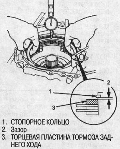
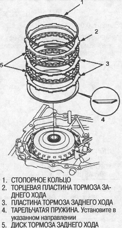
13. Starting with the reverse brake plate, install the reverse brake plates and discs in turn. Install the end plate and reverse brake circlip.
14. Use a dial gauge to measure the clearance between the end plate and the reverse brake upper disc. Set the indicator to zero by lowering the reverse brake end plate and lift it up to the retaining ring. The distance that the reverse brake end plate travels is the gap between the reverse brake end plate and the top disc. Standard: 0.45-0.75 mm.
Note: Measure at least three places and take the average as the actual gap.
15. If the gap differs from the standard, remove the reverse brake end plate and measure its thickness.
16. Select a new reverse brake end plate and install it, then recheck.
Note: If the thickest reverse brake end plate is installed but the clearance is not standard, replace the reverse brake discs and plates.
Reverse brake end plate
| plate no | catalog no | Thickness |
| 1 | 22551-P4V-003 | 3.6mm |
| 2 | 22552-P4V-003 | 3.8mm |
| 3 | 22553-P4V-003 | 4.0 mm |
| 4 | 22554-P4V-003 | 4.2mm |
| 5 | 22555-P4V-003 | 4.4mm |
| 6 | 22556-P4V-003 | 4.6 mm |
| 7 | 22557-P4V-003 | 4.8mm |
| 8 | 22558-P4V-003 | 5.0 mm |
17. After replacing the reverse brake end plate, check that the clearance is within specification.
18. Remove retaining ring, reverse brake end plate, discs and plates, and belleville spring.
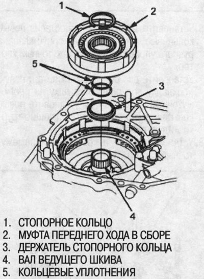
19. Install the circlip holder on the drive pulley shaft.
20. To prevent damage to the O-rings, wrap the drive pulley shaft spline with electrical tape, then install new O-rings.
21.Install the forward clutch assembly onto the drive pulley shaft, then install the circlip.
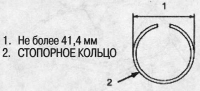
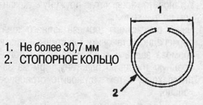
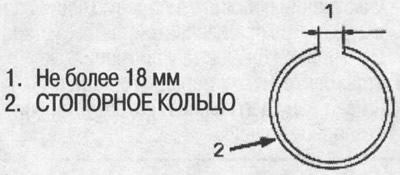
22. Check that the outside diameter of the retaining ring is correct.
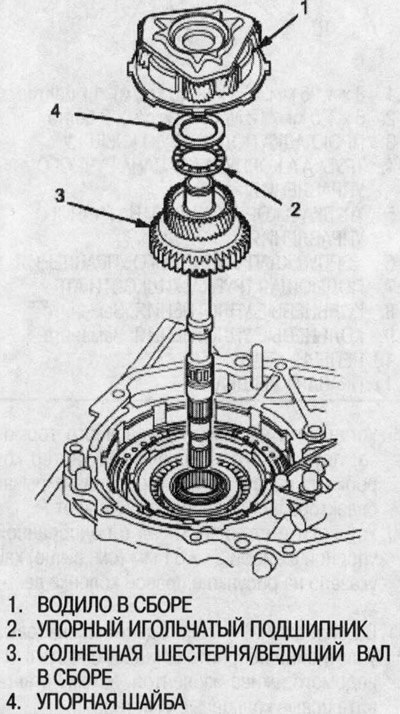
23. Install the sun gear/drive shaft assembly.
24. Install the thrust needle bearing and thrust washer on the sun gear.
25. Install the carrier assembly on the forward clutch.
26. Install thrust washer, thrust needle bearing and thrust washer to carrier assembly.
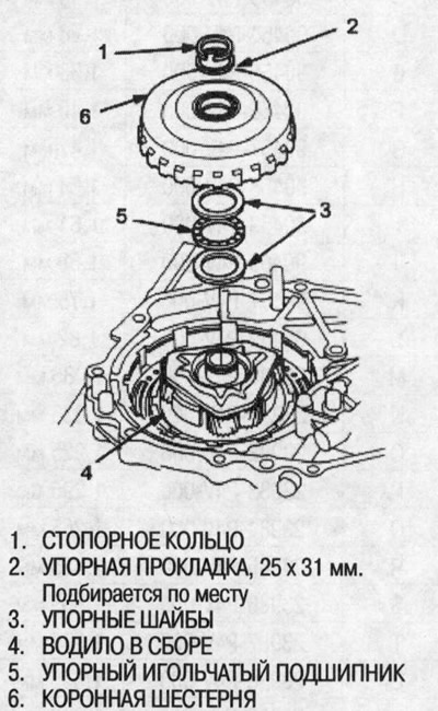
27. Install the ring gear and thrust washer 25x31mm, then install the circlip.
28. Verify that the outside diameter of the retaining ring is correct.
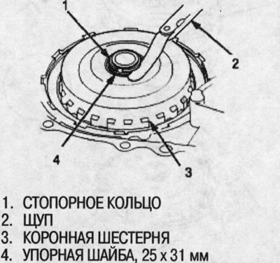
29. Measure the gap between the 25x31 mm thrust washer and the circlip. Standard: 0.05-0.11 mm.
Note: Measure at least three places and take the average as the actual gap.
30. If the gap differs from the standard, remove the 25x31 mm thrust washer and measure its thickness.
31. Pick up a new thrust washer 25x31 mm and install it, then recheck.
Thrust washer, 25x31 mm
| № | catalog no | Thickness |
| A | 90451-P4V-000 | 1.05 mm |
| IN | 90452-P4V-000 | 1.12 mm |
| WITH | 90453-P4V-000 | 1.19 mm |
| D | 90454-P4V-000 | 1.26mm |
| E | 90455-P4V-000 | 1.33 mm |
| F | 90456-P4V-000 | 1.40 mm |
| G | 90457-P4V-000 | 1.47mm |
| H | 90458-P4V-000 | 1.54 mm |
| I | 90459-P4V-000 | 1.61 mm |
| J | 90460-P4V-000 | 1.68mm |
| TO | 90461-P4V-000 | 1.75mm |
| L | 90462-P4V-000 | 1.82 mm |
| M | 23980-P4V-000 | 1.085 mm |
| N | 23981-P4V-000 | 1.055 mm |
| ABOUT | 23982-P4V-000 | 1.225 mm |
| R | 23983-P4V-000 | 1.295 mm |
| Q | 23984-P4V-000 | 1.265 mm |
| R | 23985-P4V-000 | 1.435 mm |
| S | 23986-P4V-000 | 1.505 mm |
| T | 23987-P4V-000 | 1.575 mm |
| And | 23988-P4V-000 | 1.645 mm |
| V | 23989-P4V-000 | 1.715 mm |
| W | 23990-P4V-000 | 1.785 mm |
32. After replacing the 25x31mm thrust washer, check that the clearance is within tolerance and the outside diameter of the circlip is correct as specified in step 28.
33. Install the Belleville spring in the direction shown.
34. Starting with the reverse brake plate, install the reverse brake plates and discs in turn. Install the matched reverse brake end plate, then install the circlip.
35. Be convinced that a backlash in the lock of a lock ring correct.
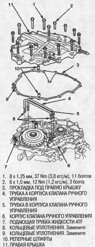
36. Install tubes A and B with new O-rings on the manual valve body and intermediate case.
37. Install two dowel pins and a new right cover gasket on the intermediate case, then install new O-rings on the ATF feed pipes.
38. Install the right cover on the intermediate crankcase.
39. Install the parking brake latch, spring and latch axle on the gearbox housing, then move the selector lever to a position other than P.
40. Install the secondary shaft with a selected thrust washer 25x31 mm (see above) as shown in the figure in the top right column.
41. To prevent damage to the O-rings, wrap the driven pulley shaft spline with electrical tape, then install new O-rings.
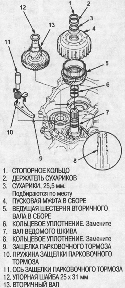
42. Assemble the output shaft drive gear assembly into the starter clutch assembly, then install them on the driven pulley shaft.
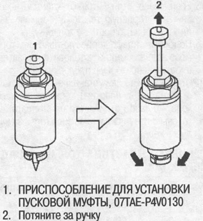
43. Pull the handle of the special tool, then insert its tip into the hole on the driven pulley shaft and install the special tool on the starting clutch.
Warning! When installing the starter clutch and output shaft drive gear assembly using the special tool, be careful not to allow dust or other foreign matter to enter the gearbox.
44. Press down on the handle of the special tool, then tighten the nut and securely seat the output shaft drive gear assembly onto the drive gear shaft.
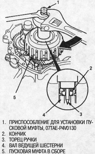
45. Pull the handle of the special tool and remove it.
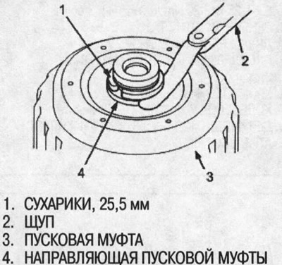
46. Install crackers, then measure the gap between the crackers and the starting clutch guide. Standard: 0-0.13 mm.
Note: Measure at least three locations and take the average as the actual gap.
47. If the gap differs from the standard, remove crackers and measure their thickness.
48. Pick up new crackers and install them, then recheck.
Croutons, 25.5 mm
| № | catalog no | Thickness |
| A | 90429-P4V-000 | 2.9mm |
| IN | 90430-P4V-000 | 3.0mm |
| WITH | 90431-P4V-000 | 3.1mm |
| D | 90432-P4V-000 | 3.2mm |
49. After replacing the 25.5 mm crackers, make sure that the gap is within the normal range.
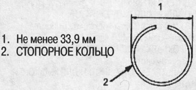
50. Install the cracker holder and retaining ring.
51.Check that the circlip outer diameter is correct.
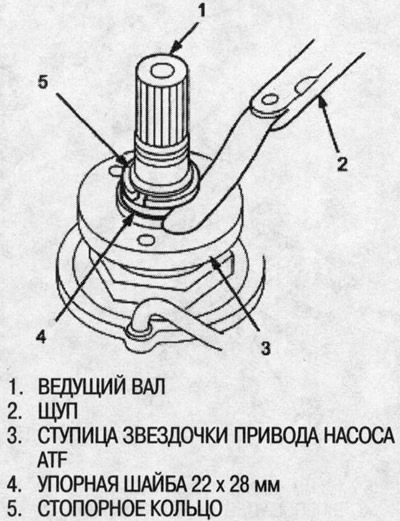
52. Install the thrust washers, ATF pump drive sprocket hub and 22 x 28 mm thrust washer onto the drive shaft, then install the circlip.
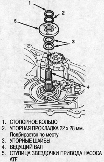
53. Check that the outside diameter of the retaining ring is correct.
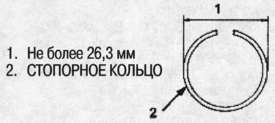
54. Measure a backlash between a persistent washer 22х28 mm and a lock ring. Standard: 0.37-0.65mm.
Note: Measure at least three places and take the average as the actual gap.
55. If the gap differs from the standard, remove the thrust washer 22x28 mm and measure its thickness.
56. Pick up a new thrust washer 22x28 mm and install it, then recheck.
Thrust washer, 22x28 mm
| № | catalog no | Thickness |
| WITH | 90573-P4V-000 | 1.15mm |
| D | 90574 P4V-000 | 1.40 mm |
| E | 90575-P4V-000 | 1.65 mm |
| F | 90576-P4V-000 | 1.90 mm |
| G | 90577-P4V-000 | 2.15mm |
| H | 90578-P4V-000 | 2.40 mm |
57. After replacing the 22mm x 28mm thrust washer, check that the clearance is within specification and that the outside diameter of the circlip is correct.
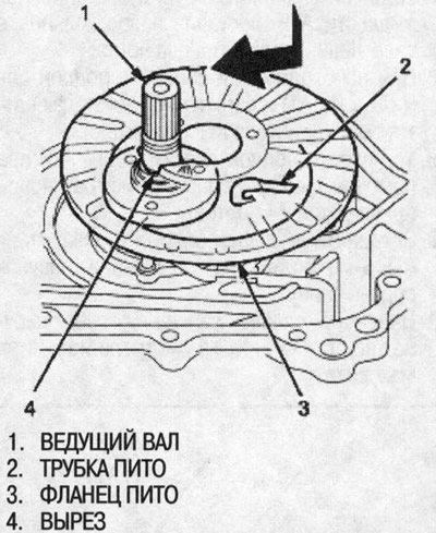
58. Install the pitot flange using its cutout as shown in the illustration so as not to obstruct the pitot tubes.
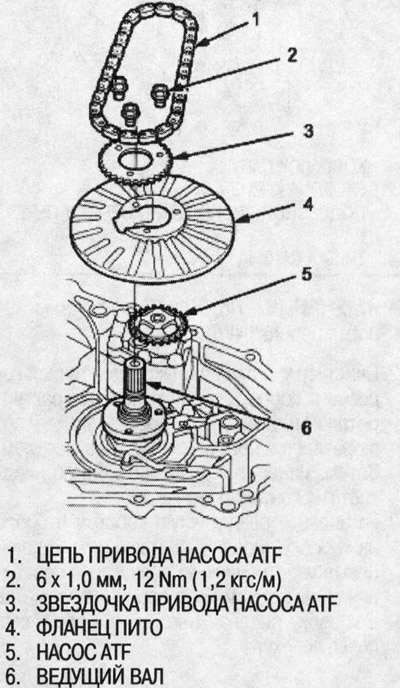
59. Install the ATF pump drive sprocket and put the ATF pump drive chain on the ATF pump drive and driven sprockets, then install and tighten the bolts (three bolts).
60. Install differential assembly.
61. Install the ATF feed pipe with new O-rings.
62. Install three dowel pins and a new flywheel gasket on the gearbox housing.
63. Install the flywheel housing to the transmission housing.
64. Install the flywheel housing mounting bolts and tighten them:
- 18 bolts and connector bracket on flywheel housing side.
- 3 bolts on the side of the gearbox housing.
65. Install the ATF feed tube holder assembly.
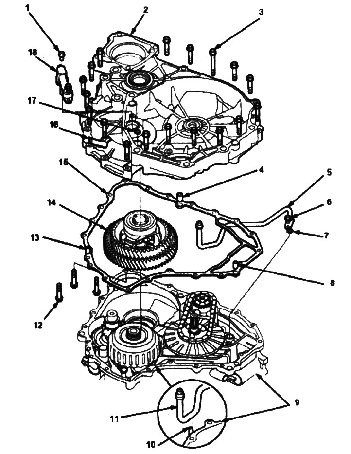
1. 6x1.0 mm, 12 Nm (1.2 kgf/m)
2. FLYWHEEL CASE
3. FLYWHEEL CASE FIXING BOLT, 8x1.25 mm, 29 Nm (3.0 kgf/m), 18 bolts
4. REFERENCE PIN, 12x20 mm
5. ATF FEED PIPE ASSEMBLY
6. 6x1.0 mm, 12 Nm (1.2 kgf/m)
7. O-ring. Replace
8. REFERENCE PIN, 10x16 mm
9. GEARBOX CASE
10. ATF FEED PIPE GUIDE
11. ATF FEED PIPE ASSEMBLY
12. FLYWHEEL CASE FIXING BOLT. 8x1.25 mm, 29 Nm (3.0 kgf/m), 3 bolts
13. REFERENCE PIN, 10x16 mm
14. DIFFERENTIAL ASSEMBLY
15. GASKET FOR FLYWHEEL CASE. Replace.
16. CONNECTOR BRACKET
17. O-ring. Replace
18. ATFBCBOPE FLUID PIPE HOLDER
66. Connect the solenoid harness connector with a new O-ring and install the lower valve manifold assembly with three alignment pins and eight bolts.
67. Install the ATF pre-filter by installing a new O-ring and tightening the two bolts.
68. If necessary, assemble the ATF sump, ATF filter and ATF cooler supply pipes (see above).
69. Install the ATF pan with two dowel pins, a new gasket and 14 bolts.
70. Attach the ATF cooler feed pipe with an 8mm bolt to the bracket.
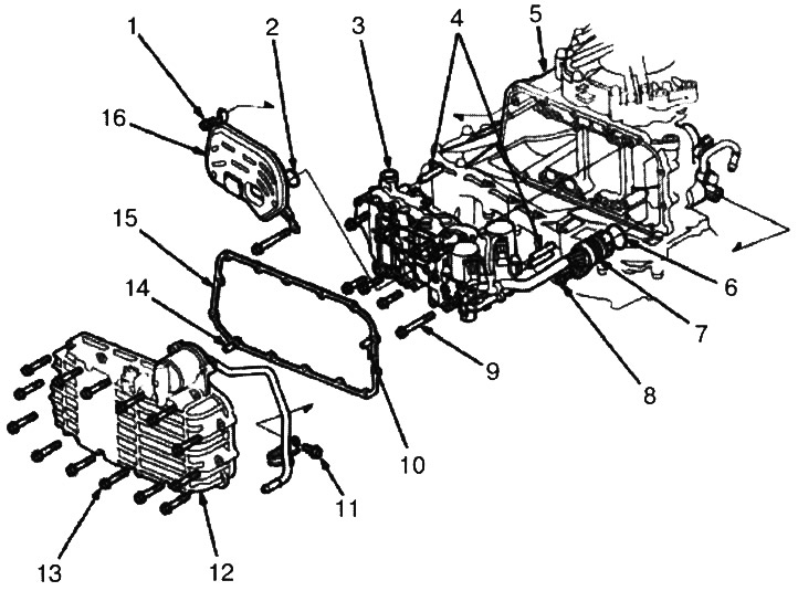
1. 6x1.0 mm, 12 Nm (1.2 kgf/m)
2. O-ring. Replace
3. LOWER VALVE BOX ASSEMBLY
4. REFERENCE PINS
5. GEARBOX CASE
6. O-ring. Replace
7. SOLENOID HARNESS CONNECTOR
8. 6x1.0 mm, 12 Nm (1.2 kgf/m)
9. 6x1.0 mm, 12 Nm (1.2 kgf/m), 8 bolts
10. REFERENCE PIN
11. BOLT FOR ATF FEED PIPE BRACKET, 8x1.25 mm, 26 Nm (2.7 kgf/m)
12. ATF PAN
13. 6x1.0 mm, 12 Nm (1.2 kgf/m), 14 bolts
14. REFERENCE PIN
15. ATF PAN GASKET Replace
16. ATF STRAINER
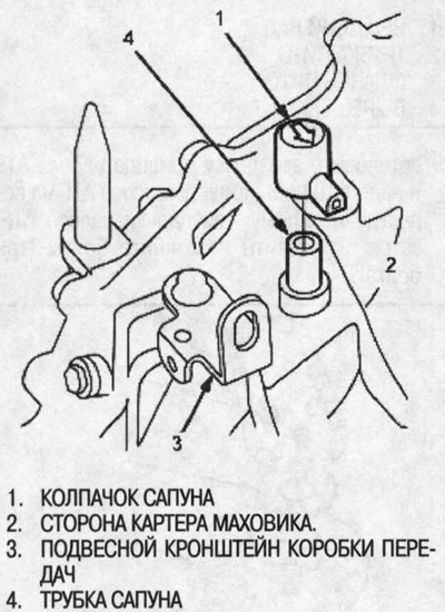
71. Put the breather cap on the breather tube so that the arrow points to the flywheel housing.
Note: Pp. 72 and 73 refer to the 4WD gearbox.
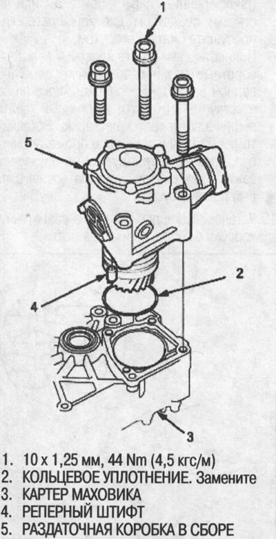
72. Clean the areas between the transfer case assembly and the gearbox with solvent or carburetor cleaner and dry with compressed air. Then apply transmission fluid to the contact areas.
73. Install the transfer case assembly to the gearbox with new O-rings. Keep dust and other foreign matter out of the gearbox.
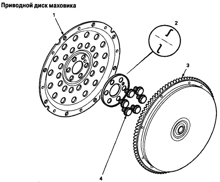
1. DRIVE DISK
2. Washer. Set in this direction
3. FLYWHEEL, Check ring gear teeth for excessive wear
4. 12x1.0 mm, 74 Nm (7.5 kgf/m). Tighten crosswise