Note: When assembling the transfer case:
- Check and adjust the shape of the contact patch of the gear teeth of the transfer case.
- Measure and adjust the clearance in the transfer case gears.
- Check and adjust the starting torque of the tapered roller bearing.
Note:
- Apply transmission fluid to all parts when assembling.
- If a tapered roller bearing or bearing outer race needs to be replaced, replace it as an assembly.
- If it is necessary to replace the drive gear or the driven gear shaft of the transfer case, replace them as an assembly.
Summary of assembly
1. Pick up a 35mm thrust washer.
Perform this procedure when replacing the transfer case driven gear shaft or tapered roller bearing on the transfer case driven gear shaft.
2. Pre-assemble all components, check and adjust the clearance in the transfer case gears and the contact patch of the teeth of the transfer case gears.
3. Disassemble the components, then assemble the transfer case driven gear shaft and related parts.
4. Measure and adjust the starting torque of the tapered roller bearing of the output gear shaft of the transfer case.
5. Assemble the transfer case shaft and related parts.
6. Measure and adjust the total starting torque.
Thrust washer selection 35 mm
1. Select a 35mm thrust washer when replacing the transfer case driven gear shaft or tapered roller bearing on the transfer case driven gear shaft.
Calculate the thickness of the 35 mm thrust washer using the following formula:
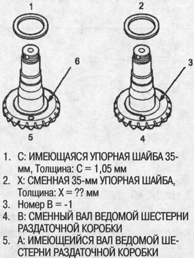
FORMULA: A/100 - B/100 + C = X
A: The number on the existing transfer case driven gear shaft.
B: Number on the transfer case driven gear shaft to be replaced.
C: Thrust washer present 35 mm thick.
X: Required thickness of replaceable thrust washer 35mm.
Note: The number on the transfer case driven gear shaft is in 1/100mm.
EXAMPLE: X \u003d A / 100 - B / 100 + C \u003d 2/100 - (-1/100) + 1.05 = 0.02 + 0.01 + 1.05 = 1.08 mm
If replacing the tapered roller bearing on the transfer case driven gear shaft, select a 1.08mm thick 35mm thrust washer.
Measure the thickness of the replacement bearing and the existing bearing and calculate the difference in bearing thickness. Correct the thickness of the existing 35mm thrust washer for differences in bearing thickness and select a replacement 35mm thrust washer.
Thrust washer, 35 mm
| Washer No | catalog no | Thickness |
| A | 41361-PS3-000 | 0.72 mm |
| IN | 41362-PS3-000 | 0.75 mm |
| WITH | 41363-PS3-000 | 0.78 mm |
| D | 41364-PS3-000 | 0.81 mm |
| E | 41365-PS3-000 | 0.84 mm |
| F | 41366-PS3-000 | 0.87 mm |
| G | 41367-PS3-000 | 0.90 mm |
| H | 41368-PS3-000 | 0.93 mm |
| I | 41369-PS3-000 | 0.96 mm |
| J | 41370-PS3-000 | 0.99 mm |
| TO | 41371-PS3-000 | 1.02 mm |
| L | 41372-PS3-000 | 1.05 mm |
| M | 41373-PS3-000 | 1.08 mm |
| N | 41374-PS3-000 | 1.11 mm |
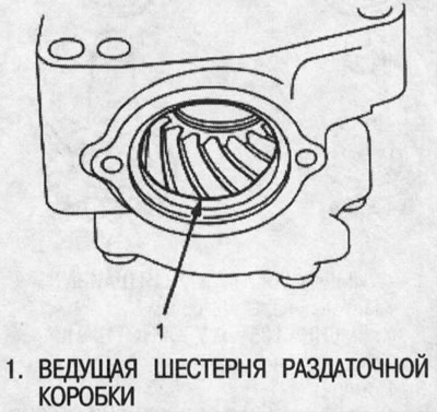
Checking the gap and shape of the contact spot of the teeth in the gears of the transfer case
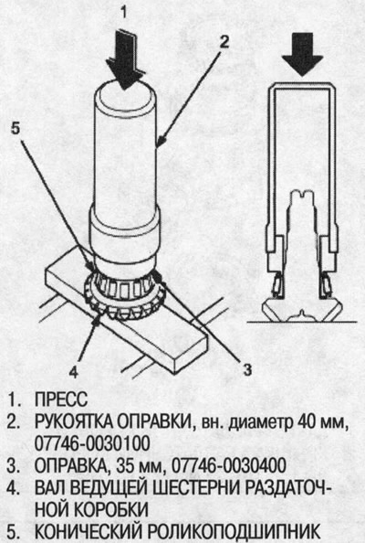
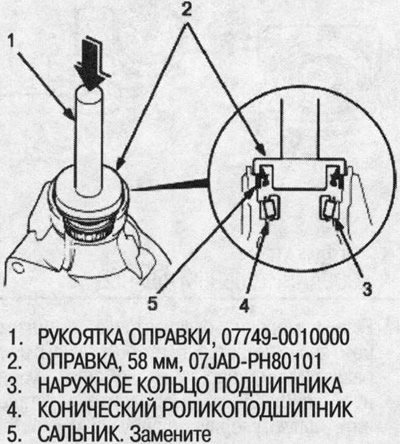
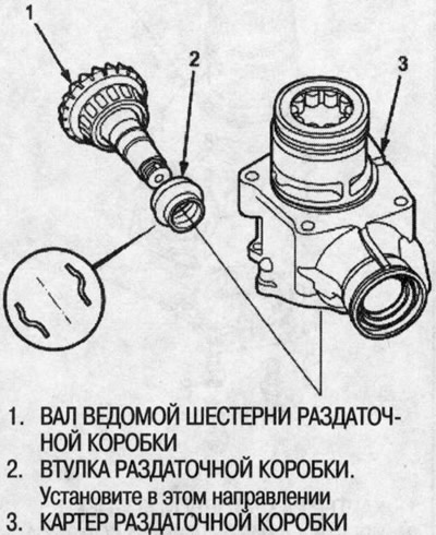
2. Install a 35mm thrust washer on the transfer case driven gear shaft, then use the special tool to press in the tapered roller bearing as shown.
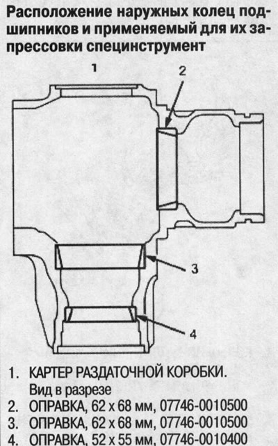
3. Place the tapered roller bearing on the bearing outer race at the transfer case housing connecting flange side.
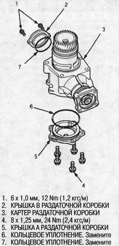
4. Using the special tool, press a new oil seal into the transfer case housing.
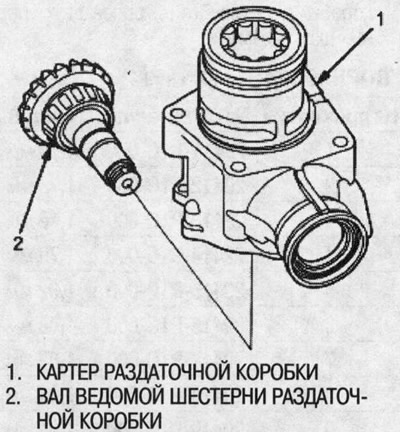
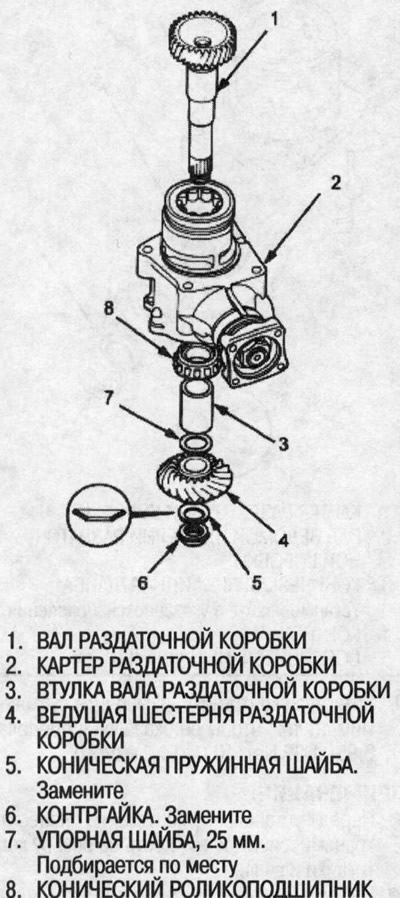
5. Install the transfer case driven gear shaft into the transfer case housing. At this stage, do not install the transfer case bushing onto the transfer case driven gear shaft.
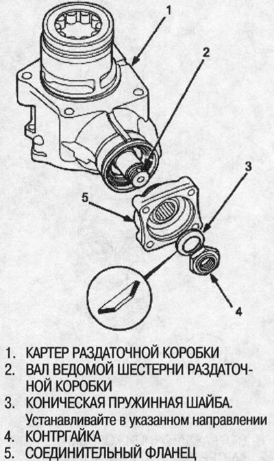
6. Install the connecting flange, conical spring washer and locknut on the transfer case driven gear shaft. Do not install the O-ring and protective ring on the transfer case shaft at this stage.
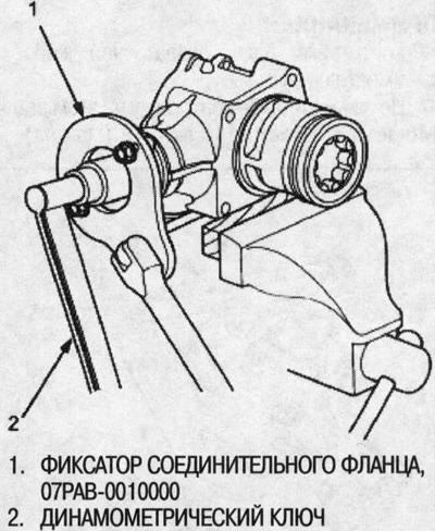
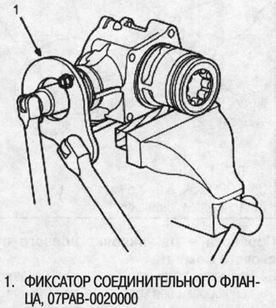
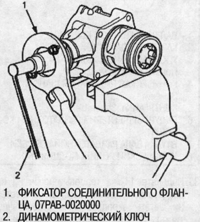
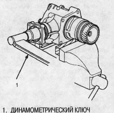
7. Secure the transfer case housing in a soft jaw vise, then install the special tool on the connecting flange. To prevent damage to the transfer case housing, always secure it in a soft jaw vise or insert gasket material between the vise and transfer case.
8. Tightening the locknut, measure the starting torque so that it is between 0.98-1.39 Nm (10.0-14.2 kgf/cm)
Note:
- Before installing the locknut, apply transmission fluid to the threads of the locknut and shaft.
- Do not caulk the locknut at this stage.
Starting torque: 0.98-1.39 Nm (10.0-14.2 kgf/cm).
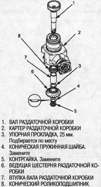
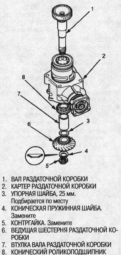
9. Install the transfer case shaft into the transfer case housing, then install the tapered roller bearing, transfer case shaft bushing, 25mm thrust washer, transfer case drive gear, conical spring washer and locknut onto the transfer case shaft (figure on the next page at the top of the left column).
Note:
- Before installing the locknut, apply transmission fluid to the threads of the locknut and shaft.
- Do not caulk the locknut at this stage.
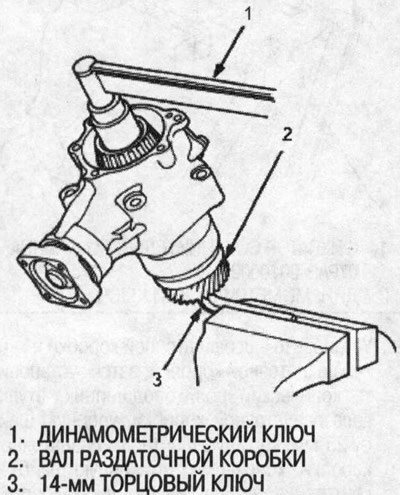
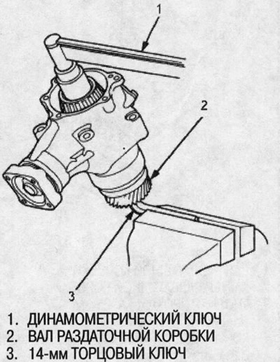
10. Install a 14mm socket wrench onto the gear side of the transfer case shaft, then secure the wrench in a bench vise.
11.Tighten the locknut on the transfer box shaft. Tightening torque: 118 Nm (12.0 kgf/m).
Note:
- The transfer case shaft locknut has a left-hand thread.
- Do not caulk the locknut at this stage.
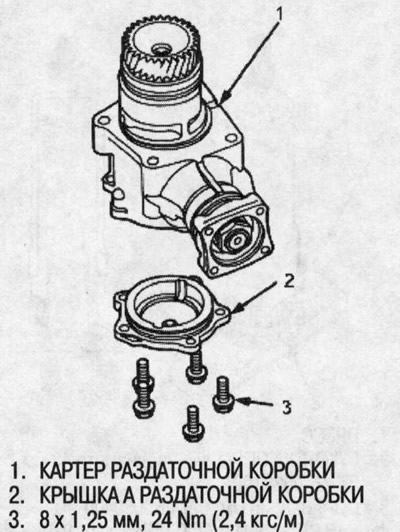
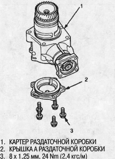
12. Temporarily install transfer case cover A without O-ring.
13. Rotate the connecting flange several times to seat the tapered roller bearing.
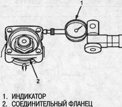
14. Install the indicator head on the connecting flange, then measure the clearance in the transfer case gear. Standard: 0.06-0.16mm
15. If the measurement differs from the standard value, unscrew the lock nut from the transfer case shaft and replace the 25 mm thrust washer. Select and install a new 25mm thrust washer, then measure again. To adjust the clearance in the transfer case gear, use no more than two 25 mm thrust washers.
Thrust washer, 25 mm
| Gasket No | catalog no | Thickness |
| 1 | 29411-Р1С-000 | 1.70 mm |
| 2 | 29412-Р1С-000 | 1.73mm |
| 3 | 29413-Р1С-000 | 1.76 mm |
| 4 | 29414-Р1С-000 | 1.79 mm |
| 5 | 29415-Р1С-000 | 1.82 mm |
| 6 | 29416-Р1С-000 | 1.85 mm |
| 7 | 29417-Р1С-000 | 1.88mm |
| 8 | 29418-Р1С-000 | 1.91 mm |
| 9 | 29419-Р1С-000 | 1.94 mm |
| 10 | 29420-Р1С-000 | 1.97 mm |
| 11 | 29421-Р1С-000 | 2.00 mm |
| 12 | 29422-Р1С-000 | 2.03mm |
| 13 | 29423-Р1С-000 | 2.06mm |
| 14 | 29424-Р1С-000 | 2.09 mm |
| 15 | 29425-Р1С-000 | 2.12mm |
| 16 | 29426-Р1С-000 | 2.15mm |
| 17 | 29427-Р1С-000 | 2.18mm |
| 18 | 29428-Р1С-000 | 2.21 mm |
| 19 | 29429-Р1С-000 | 2.24mm |
16. Apply a thin layer of red lead evenly on both sides of the transfer case gear teeth.
17. Rotate the coupling flange in both directions until the transfer case gear has rotated one full turn in both directions.
18. Check the shape of the contact patch on the gear teeth of the transfer case.
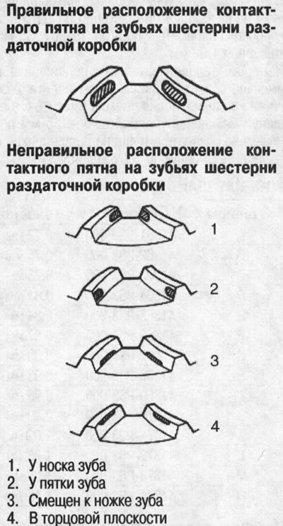
19. If the contact pattern on the transfer case gear teeth is incorrect, adjust it with a 35mm or 25mm thrust washer.
Note:
- See 35mm thrust washer selection procedure above.
- Use no more than two 35mm thrust washers to adjust the contact patch on the transfer case gear teeth.
- See 25mm thrust washer selection procedure above.
- Use no more than two 25mm thrust washers to adjust the contact patch on the transfer case gear teeth.
Toe contact
Use a thicker 35mm thrust washer to move the transfer case driven gear shaft towards the drive gear. Because this movement changes the clearance in the transfer case drive gear, to adjust the clearance in the transfer case gear, move the drive gear away from the driven gear shaft as follows:
- Increase the thickness of the thrust washer to 25mm.
- Decrease the thickness by the increase in thickness of the 25mm thrust washer.
Contact at the heel of the prong
Use a thinner 35mm thrust washer to move the transfer case driven gear shaft away from the drive gear. Because this movement changes the clearance in the transfer case drive gear, to adjust the clearance in the transfer case gear, move the drive gear sideways towards the driven gear shaft as follows:
- Reduce the thickness of the thrust washer 25mm.
- Increase the thickness of the 68mm thrust washer by the reduction in thickness of the 25mm thrust washer.
Contact patch shifted to the tooth root
Use a thinner thrust washer to move the drive gear sideways towards the transfer case driven gear shaft. The contact patch shifted to the tooth root must be adjusted within the gap in the transfer case drive gear. If the gap exceeds the limits, adjust as described for the contact at the heel of the tooth.
End plane contact
Use a thicker thrust washer to move the drive gear away from the transfer case driven gear shaft. The contact in the end plane must be adjusted within the gap in the transfer case drive gear. If the gap is out of range, adjust as described for tooth toe contact.
20. Remove the components from the transfer case shaft and remove the transfer case shaft from the transfer case housing.
Checking and adjusting the starting torque of the driven gear shaft of the transfer case
21. Secure the transfer case housing in a soft-jawed vise. To prevent damage to the transfer case housing, always secure it in a soft jaw vise or insert gasket material between the vise and transfer case.
22. Install the special tool on the connecting flange, then unscrew the locknut from the transfer case driven gear shaft and remove the conical spring washer.
23. Remove the transfer case driven gear shaft and connecting flange.
24. Install a new bushing on the transfer case driven gear shaft, then install them in the transfer case housing.
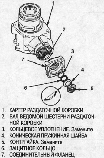
25. Install the connecting flange, O-ring, protective ring, conical spring washer and locknut on the transfer case driven gear shaft.
Note:
- Before installing the locknut, apply transmission fluid to the threads of the locknut and transfer case shaft.
- Install the conical spring washer in the direction shown.
26. Secure the transfer case housing in a soft-jawed vise. To prevent damage to the transfer case housing, always secure it in a soft jaw vise or insert gasket material between the vise and transfer case.
27. Install the special tool on the connecting flange, then tighten the locknut on the shaft of the driven gear of the transfer case, measure the starting torque.
- Starting torque: 0.98-1.39 Nm (10.0-14.2 kgf/cm)
- Tightening torque: 132-216 Nm (13.5-22.0 kgf/m)
Note:
- Rotate the connecting flange to seat the tapered roller bearing, then measure the starting torque.
- If the starting torque exceeds 1.39 Nm (14.2 kgf/cm), replace the transfer case bushing and assemble the components. Do not adjust the starting torque with the lock nut loose.
- If the tightening torque exceeds 216 Nm (22.0 kgf/m), replace the transfer case bushing and assemble the components.
- Record the starting torque measurements; they are useful when measuring total starting torque.
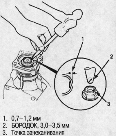
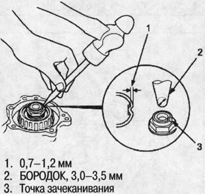
28. Locate the locknut on the transfer case driven gear shaft with a 3.5mm barb as shown.
29. Install the transfer case shaft into the transfer case housing, then install the tapered roller bearing, transfer case shaft bushing, 25mm thrust washer, transfer case drive gear, conical spring washer and locknut onto the transfer case shaft.
Note:
- Before installing the locknut, apply transmission fluid to the threads of the locknut and shaft.
- Install the conical spring washer in the direction shown.
30. Install a 14mm socket wrench onto the gear side of the transfer case shaft, then secure the wrench in a bench vise. Tighten the transfer box shaft locknut. (The locknut has a left-hand thread). Tightening torque: 118 Nm (12.0 kgf/m).
31.Crack the locknut on the transfer case shaft with a 3.5mm barb.
Checking and adjusting the total starting torque
32. Temporarily install transfer case cover A without O-ring.
33. Secure the transfer case housing in a soft-jawed vise, then turn the connecting flange a few times to seat the tapered roller bearing. To prevent damage to the transfer case housing, always secure it in a soft jaw vise or insert gasket material between the vise and transfer case.
34. Measure the total starting torque. Total starting torque: 1.70-2.08 Nm (17.3-21.2 kgf/cm) + the value of the starting torque of the shaft of the driven gear of the transfer case (written in paragraph 27).
35. Remove cover A of the transfer case.
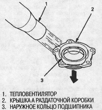
36. If the measurement is out of tolerance, remove the 68mm thrust washer from transfer case cover A by heating the cover to nearly 100°C with a fan heater. Do not heat the lid above 100°C. Allow the lid to cool to room temperature before adjusting the starting torque. If the measurement is out of tolerance, go to step 40.
37. Pick up a 68mm thrust washer.
Thrust washer, 68 mm
| Gasket No | catalog no | Thickness |
| ZV | 23974-Р1С-020 | 1.41 mm |
| ZW | 23975-Р1С-020 | 1.44mm |
| ZX | 23976-Р1С-020 | 1.47mm |
| ZY | 23977-Р1С-020 | 1.50 mm |
| TL | 23978-Р1С-020 | 1.53 mm |
| A | 23941-PW5-000 | 1.56mm |
| IN | 23942-PW5-000 | 1.59 mm |
| WITH | 23943-PW5-000 | 1.62 mm |
| D | 23944- PW5-000 | 1.65 mm |
| E | 23945-FW5-000 | 1.68mm |
| F | 23946-PW5-000 | 1.71 mm |
| G | 23947-PW5-000 | 1.74mm |
| H | 23948-PW5-000 | 1.77mm |
| 1 | 23949-PW5-000 | 1.80 mm |
| J | 23950-PW5-000 | 1.83 mm |
| TO | 23951-PW5-000 | 1.86 mm |
| L | 23952-PW5-000 | 1.89 mm |
| M | 23953-PW5-000 | 1.92 mm |
| N | 23954-PW5-000 | 1.95 mm |
| 0 | 23955-FW5-000 | 1.98 mm |
| R | 23956-PW5-000 | 2.01mm |
| Q | 23957-PW5-000 | 2.04mm |
| R | 23958-PW5-000 | 2.07mm |
| S | 23959-PW5-000 | 2.10 mm |
| T | 23960-PW5-000 | 2.13mm |
| And | 23961-PW5-000 | 2.16mm |
| V | 23962-PW5-000 | 2.19 mm |
| W | 23963-PW5-000 | 2.22mm |
| X | 23964-PW5-000 | 2.25mm |
| At | 23965-PW5-000 | 2.28 mm |
| Z | 23966-PW5-000 | 2.31mm |
| AA | 23967-PW5-000 | 2.34mm |
| AB | 23968-PW5-000 | 2.37mm |
| AC | 23969-PW5-000 | 2.40 mm |
| AD | 23970-PW5-000 | 2.43mm |
| AZ | 23971-PW5-000 | 2.46mm |
| BZ | 23972-PW5-000 | 2.49 mm |
| CZ | 23973-PW5-000 | 2.52 mm |
| DZ | 23974-PW5-000 | 2.55mm |
| EZ | 23975-PW5-000 | 2.58mm |
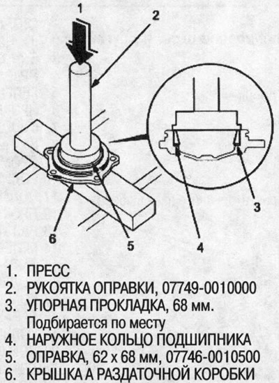
38. Using the special tool, press in the 68mm thrust washer.
39. After replacing the 68mm thrust washer, recheck to ensure that the total starting torque is within tolerance.
40. Install the O-rings on covers A and B of the transfer case.