
WARNING: Requires special tools or equivalent. A hydraulic press, punches of the correct diameter, and support stands are required to disassemble the hub and bearing. (Honda special tool numbers are shown)
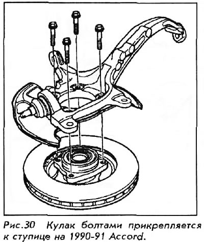
See also figures 23 and 24.
1. Remove the spindle nut pin from the spindle and loosen the nut. Do not tighten or loosen the spindle nut unless the vehicle is on all 4 wheels. The required torque is high enough to cause the vehicle to fall off the stand even when properly secured.
2. Raise and securely support the vehicle.
3. Remove the wheel and spindle nut.
4. Remove the caliper by unscrewing the mounting bolts. Secure the caliper outside the work area with a wire. Do not leave the caliper hanging on the brake hose.
5. Remove the cotter pin from the tie rod castle nut and remove the nut. Separate the tie rod ball joint using a ball joint remover, then remove the tie rod from the knuckle.
6. Remove the cotter pin and loosen the lower control arm ball joint nut by half the thread length. The nut will hold the control arm in place while the joint loosens.
7. Separate the ball joint and the lower arm using a puller, grasping the lower arm with the pawls.
Avoid damaging the ball joint boot. If necessary, use penetrating lubricant to loosen the ball joint.
8. Move the knuckle to the side and remove the outer axle joint from the knuckle.
9. Remove the cotter pin and nut from the upper ball joint. Separate the upper ball joint.
Avoid damaging the ball joint boot. If necessary, use penetrating lubricant to loosen the ball joint.
10. Unscrew the four bolts and remove the knuckle from the hub assembly.
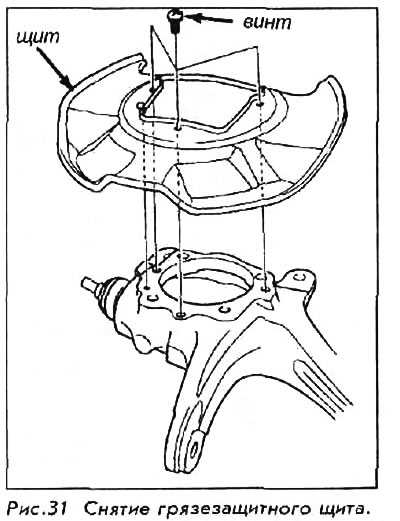
11. Remove the mud shield from the fist.
12. Unscrew the four bolts and separate the hub assembly from the brake disc.

13. Install the hub in the hydraulic press. Press the wheel bearing out of the hub while supporting it.
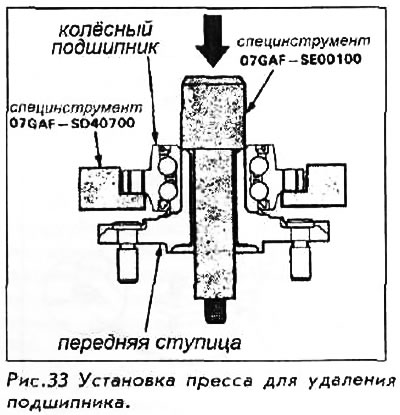
14. Remove the outer bearing inner race from the hub using a bearing puller.
After removal, the bearing must be replaced with a new one.
To install:
15. Thoroughly clean the knuckle and hub.
16. Install the hub in a hydraulic press. Press the new wheel bearing into the hub using a drift of the appropriate diameter.
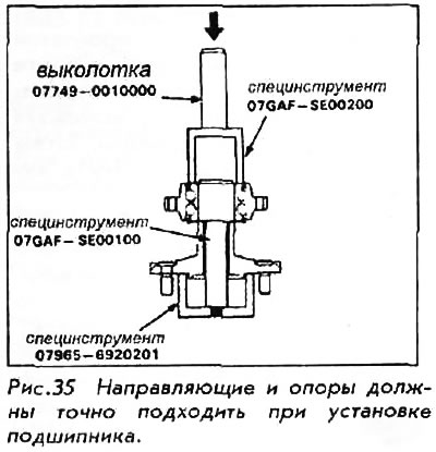
17. Install the hub on the brake disc and tighten the bolts to 55 Nm.
18. Install the mudguard.
19. Install the knuckle onto the hub; tighten the bolts to 45 Nm.
20. Install the knuckle/hub assembly to the vehicle. Tighten the upper ball joint nut and tie rod nut to 44 Nm and install new cotter pins. Tighten the lower ball joint nut to 55 Nm and install a new cotter pin.
21. With the vehicle lowered to the ground on all 4 wheels, install a new spindle nut and tighten it to 245 Nm.