
Air conditioning system
Attention! The air conditioning system is constantly under high pressure. Never disconnect refrigeration lines or remove any system components without first discharging the system. The discharge of the air conditioning system must be carried out by an experienced specialist in a car service workshop. Always wear safety goggles when disconnecting refrigerant lines!
When replacing air conditioning system components, a certain amount of replacement refrigerant oil will be required to fill the volume of the new assembly. Use only oil suitable for use in R-134a systems (read the label on the container carefully).
Service

The following checks should be carried out on a regular basis to keep the air conditioning system in good working order:
- a) Check the condition of the compressor drive belt. If defects or signs of wear are found, replace (see chapter Settings and ongoing maintenance);
- b) Check drive belt tension, adjust if necessary (see chapter Settings and ongoing maintenance);
- c) Check the refrigeration hoses for cracks, swelling, signs of hardening and aging of the rubber. Replace if necessary;
- d) Check the condenser plates for insect remains, old leaves, and other debris stuck between them. If necessary, clean the gaps with a thin brush, or blow them with compressed air;
- e) Check system charge level;
- f) If water drips are found on the floor mats under the instrument panel, remove the condensate drain pipe from the evaporator casing (located in the lower front corner) and a piece of wire, check the patency of both holes. The air conditioning system must be switched on for at least 10 minutes at least once a month (even in the winter season). Prolonged inactivity of the A / C leads to hardening and failure of the sealing rings and cuffs of the connecting path.
Note. When the deicing function is activated, the A/C compressor is activated.
In case of irregularities in the operation of the A/C, first of all check the correct operation of the compressor clutch (see Section Check of an electric chain of coupling of coupling of the compressor K/V).
Due to the complexity of the system design and the need to use special equipment, its maintenance, in-depth diagnostics and refurbishment are beyond the qualifications of an average amateur mechanic and must be carried out in a car service workshop. Only the simplest checks and replacements listed below in this Section fall within the competence of the owner of the car.
The most typical cause of a malfunction in the functioning of the A/C is a decrease in the charge level of the refrigerant oil. The following simple checks will quickly identify signs of a low refrigerant level.
Examination
1. Warm up the engine to normal operating temperature.
2. Turn on the A/C for maximum cooling capacity. Select the maximum fan speed. Open the doors to prevent closed air circulation in the cabin.
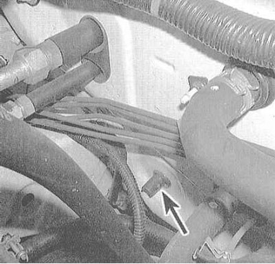
3. After the temperature of the system reaches the operating temperature, feel the two tubes connected to the evaporator on the bulkhead of the engine compartment.
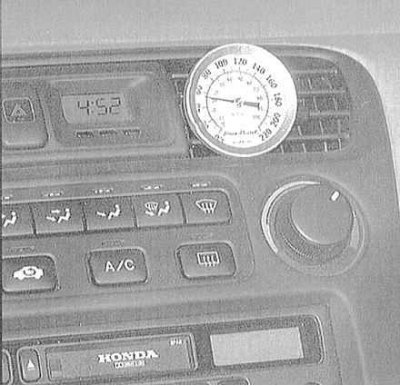
4. The thinner tube leading to the evaporator from the condenser outlet should feel cold enough to the touch. The thicker tube from the evaporator outlet to the back of the compressor should be a little colder (by 2÷6 degrees). If the exhaust pipe is noticeably warmer to the touch than the inlet, then the system needs to be recharged. Insert the thermometer into the air outlet duct through the central vent on the instrument panel. When the A/C is on, the temperature of the air leaving the deflector should be 19 ÷ 22 degrees lower than the ambient temperature (up to 4.5°С). In very hot weather (+40°С), it is permissible to increase the output temperature to a level of 15.6°C, but no more.
5. If the requirements listed in the previous paragraph are not met, then the system needs to be charged. For a more detailed diagnosis of the state of the system, the car should be driven to a specialized workshop. Performing some on-board diagnostic checks will determine the nature of the damage and the amount of restoration work to be done.
Adding refrigerant
Attention! To charge the air conditioning system of the vehicles covered in this manual, use only refrigerant oil R-134a.
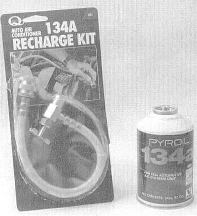
1. Prepare the standard charger kit R-134a (ask at car accessories stores). The set includes a bottle of refrigerant oil, a valve nozzle and a piece of hose connected between the valve and the fitting of the low-pressure part of the refrigeration tract (see accompanying illustration). Since one can of oil may not be enough to fully charge the system, it makes sense to buy a couple at once just in case. Make sure that at least one of the cans is tinted with red oil, which will allow you to quickly identify refrigerant leaks if they occur.
Attention! Never fill the system with more than two cans of refrigerant!
2. Connect the charging kit to the system according to the manufacturers instructions.
Attention! Do not attempt to connect the kit to the fitting of the high-pressure part of the duct! The design of the fitting connections allows the set to be connected only to the low-pressure part of the system.
3. Close the valve on the adapter and screw the adapter onto the cartridge head, making sure that the o-ring/rubber gasket is present.
Attention! Be sure to wear safety goggles!
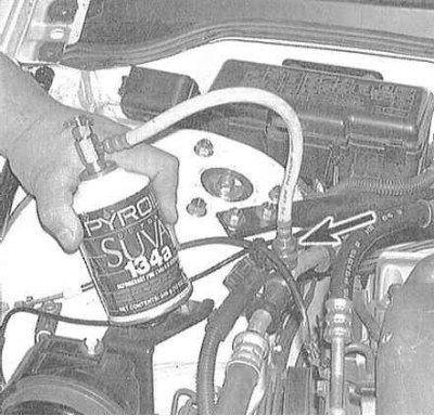
4. Remove the dust cap from the low-pressure refrigeration line connection and connect the charging set hose equipped with a quick connector to it.
5. Warm up the engine and turn on the A/C. Ensure that the charging kit hose does not come into contact with the engine cooling/air conditioning fan blades.
Note. Charging the system must be done with the compressor running. If the compressor clutch disengages, the system should be switched to maximum cooling capacity and all passenger compartment doors should be opened.
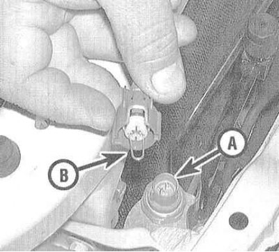
To prevent the compressor from turning off during charging, disconnect the connector from the low pressure switch (some models use a combined low/high pressure sensor/switch) and bridge it with a paper clip or a piece of stiff wire.
6. Rotate the valve nozzle to pierce the head of the cartridge, thereby opening the refrigerant supply (you should hear the characteristic sound of escaping gas). During the entire charge, hold the can strictly upright, shaking it from time to time. Between charging series, pause to allow the system to stabilize.
7. If you have an accurate thermometer at hand, insert it through the deflector into the central air duct K / V and follow it for the temperature of the air supplied to the passenger compartment.
8. When the cartridge is empty, close the valve and disconnect the hose from the system's low-pressure fitting. Replace the dust cap immediately.
9. Disconnect the valve nozzle from the cartridge, if necessary, move it to the second cartridge and continue filling. Upon completion of the procedure, place the unfinished cartridge upright on the rack and use it as needed to recharge the system.
Heating system
Moistening of the carpet on the floor under the heater heat exchanger, or steam escaping through the air duct deflectors, indicate heat exchanger leaks. Remove heat exchanger (see Section Removal and installation of the heater heat exchanger) and replace it with a new one (the heater heat exchanger cannot be repaired).
If the heater does not provide adequate heating of the air supplied to the passenger compartment, the reason for such a failure may be one of the following:
- a) The thermostat is stuck in the open position, which does not allow the engine coolant supplied to the heat exchanger of the heater to warm up to normal temperature;
- b) There is a violation of the patency of the cooling tract, which blocks the supply of coolant to the heater heat exchanger. Feel the hoses connected to the nozzles on the rear bulkhead of the engine compartment - both of them must be hot, otherwise the patency of the tract is broken (blocked hoses, heat exchanger, or heater control damper). Disconnect the hoses and back-flush the heat exchanger. Having previously disconnected, also flush both hoses;
- c) If it is not possible to restore the patency of the heat exchanger by flushing, the unit should be replaced.
On-board diagnostics
Standard heating/air conditioning system
On the models considered in this manual, diagnostics of failures in the electrical circuit of the heater / air conditioner control device can be made without the use of a scanner reader.
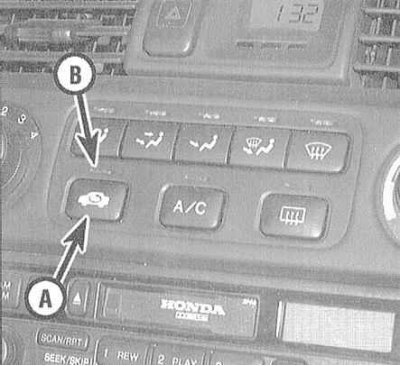
Turn on the ignition and, by pressing the button for initiating the closed recirculation mode, turn on the control lamp located directly above it. The heater fan must be turned off. Click the button again (the control lamp should go out) and keep it pressed down. The repeated switching on of the control lamp indicates the initiation of the self-diagnosis mode. Now the lamp will begin to display the codes of the simplest malfunctions detected in the system. One flash indicates a malfunction of the air mixing process control electric motor (damper jamming, winding failure, or short circuit). Two flashes mean the failure of the mode selection control electric motor. Three flashes indicate violations associated with open or short circuits in the evaporator temperature sensor circuit, or an internal malfunction of the sensor assembly itself.
Air Mixing Motor Circuit

Disconnect the electrical wiring from the motor assembly. Using a jumper wire, apply battery voltage to terminal 1 of the motor connector, terminal 2 to ground. The motor should start to rotate, otherwise swap the jumper wires, which should cause the motor to rotate in the opposite direction. A defective motor must be replaced. Next, measure the resistance between terminals 5 and 7 of the connector (the required value is 4.2÷7.8 kΩ) and terminals 3 and 5 (0.58÷1.09 kOhm when cold air is supplied to the passenger compartment and 3.52÷6.55 kOhm when the maximum heating intensity mode is selected). If there is any doubt about the correct operation of the damper, disconnect the drive rod of the electric motor from the actuating rod and repeat the test described above using jumper wires. If now the motor starts to function properly, replace the damper or its rod.
Mode selection electric motor
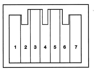
The test is made by applying battery voltage to terminal 2 and grounding terminal 1 of the motor. The motor should turn to the stop and stop, after which the power supply should be immediately disconnected. Reversing the polarity of the jumper wires should cause the motor to rotate in the opposite direction. If you have a universal circuit meter with a digital indicator at hand, turn on the device in the resistance measurement mode (range up to 20 kΩ with output current less than 1 mA) and check for continuity between the terminals of the connector during the procedure). There should be instantaneous continuity between terminal 7 and terminals 3, 4, 5 and 6.
If the electric motor rotates too slowly, or does not rotate at all, disconnect its drive rods for the corresponding damper and repeat the test. If now the rotation is normal, try to identify and eliminate the cause of the damper jamming or its thrust.
Electric motor for switching on the closed air circulation mode
Disconnect wiring from motor.
Using a jumper wire, apply battery voltage to terminal 1 of the electric motor, ground terminals 5 and 7 to ground. The motor should begin to rotate smoothly and go to one of its two extreme positions ("closed circulation" or "Outside air supply") when disconnecting the mass.
If the electric motor rotates too slowly, or does not rotate at all, disconnect its drive rods for the corresponding damper and repeat the test. If now the rotation is normal, try to identify and eliminate the cause of the damper jamming or its thrust.
Models equipped with a climate control system
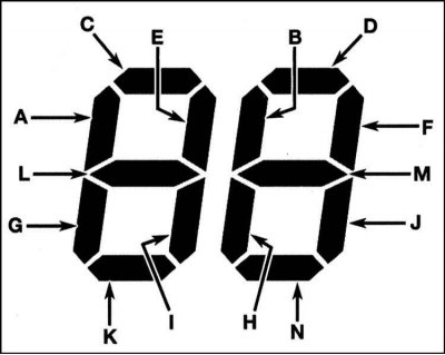
These models use a more sophisticated self-diagnosis system. As an indicator, instead of a control lamp, an LED display of the control panel temperature gauge is used, capable of displaying up to 40 fault codes. During the diagnostic test, the display will show two symbols in the form of the number 88. Each of the segments of both symbols is responsible for a certain failure in the system. Wait one minute, then press the button "AUTO" on the control panel. Holding down the button "AUTO" pressed, also press the button "OFF", the display of the temperature gauge should show two characters in the form of the number 88.
If the self-diagnostic device detects one of the standard failures in the system, the corresponding segment of one of the symbols flashes. In accordance with the symbols shown in the illustration above, write down the symbols of the flashing sectors of the display. By referring to the fault code map, determine the nature of the failure and get ready to carry out the appropriate remedial repair.
Eliminate air conditioning odors
Unpleasant odors that often occur when A/C is turned on are caused by the formation of mold colonies on the plates of the evaporator heat exchanger. A warm, humid environment creates the most favorable conditions for the emergence and development of fungal microorganisms.
Access to the evaporator heat exchanger on most models is extremely limited. The procedure for guaranteed complete removal of mold, performed in a car service workshop, is quite laborious, time-consuming and requires the use of strong disinfectants. In principle, sufficiently effective processing can be performed at home by the owner of the car on his own.
Specialty aerosol disinfectants designed for servicing air conditioning systems can be purchased at almost any auto accessories store. It should be remembered that the price of a tool is usually directly proportional to its effectiveness. Switch the system to closed air circulation mode and turn on the heater fan at maximum speed for ten minutes. In order to dry the system, turn on the heating to maximum intensity. Disconnect the electrical wiring from the compressor in order to prevent its operation (see Section Removal and installation of the K/V compressor).
The supply of the product is usually carried out through a long hose. Remove the heater fan motor (see Section Removal and installation of the electric motor of the heater fan drive), insert the nozzle of the supply nozzle into the resulting hole and move it to the left, pointing at the evaporator heat exchanger. The supply of the product is carried out in accordance with the instructions of its manufacturer. Try to treat the entire surface of the heat exchanger as completely as possible. The duration of each processing cycle and the intervals between series must be indicated on the container label.
The best preventive measure against the formation of mold colonies in the evaporator heat exchanger is to regularly check the patency of the drain tube.