
Note: The illustration shows a left-hand drive model; the location on the right-hand drive model is symmetrical.
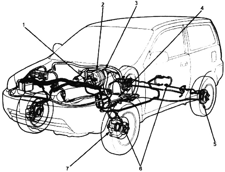
1. MAIN CYLINDER
Removal/Installation (see below)
Master cylinder disassembly (see below)
Master cylinder assembly (see below)
pumping (see below)
Testing the brake fluid level sensor (see below)
Push rod gap adjustment (see below)
2. INDICATOR
Brake Indicator Wiring Diagram (see below)
2. VACUUM BRAKE BOOSTER
Removal / Installation (see below)
Checking the brake booster (see below)
3. BRAKE PEDAL
Check and adjustment (see below)
4. PARKING BRAKE LEVER
Check and adjustment (see below)
Testing the parking brake switch (see below)
4. PARK BRAKE CABLE. Check / Replace (see below)
5. REAR WHEEL DRUM BRAKES
Pointer / Check (see below)
Replacement of brake pads (see below)
5. WORKING CYLINDER. Disassembly / Inspection (see below)
6. BRAKE HOSES/PIPES
Check / Tightening torques (see below)
Hose replacement (see below)
7. FRONT BRAKES
brake pads (see below)
Brake disk (see below)
Stopping support (see below)