
Models without remote control
The operation of the system is based on the operation of individual lock activators for each of the car doors. The system consists of control switches, door actuators and connecting wiring. Diagnosis of lock failures is limited to checking the condition of the contact connections of the electrical circuit and the correct operation of the door activators.
The functioning of a single lock occurs due to the operation of bidirectional electromagnets located in the car doors. The control switch has two positions: LOCKED and OPEN. On later models equipped with a remote control for door actuators, a control module is also provided that provides voltage to the lock actuators on command from the remote control. When activated, the switch sends a ground signal to the door lock control unit, resulting in the appropriate switching of the actuators. Depending on the initial position of the switch, when it is switched, the control unit simply reverses the polarity of the current supplied to the electromagnets. On models without a remote control, the switches act directly on the activators.
If you cannot find the cause of the system failure during the checks listed below, drive the car to a workshop for a more complete diagnosis.
Always check the condition of the loop protection first. On the models under consideration, circuit protection is provided by fuses 6 and 13, placed in the mounting block located on the right under the instrument panel, and fuse 9, in the left mounting block.
Toggle the control switches in both directions with the engine off. Listen for clicks that accompany the relay operation.
If there are no clicks, check the power supply to the switches. If there is no voltage, check the condition of the wiring in the section of the circuit between the mounting block and the corresponding switch.
If there is voltage but no click is heard, check the continuity of the switch in both positions. Defective switches must be replaced.
If the switch is in order, check the conductivity of the wiring in the section of the circuit between the switch and the electromagnet of the corresponding activator. Repair damaged wiring.
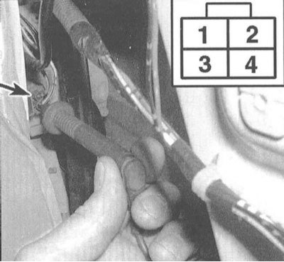
If only one of the activators fails, remove the interior upholstery panel from the corresponding door (see chapter Body) and check the correctness of the voltage supply to the executive electromagnet by switching the control switch. One of the wires must be powered in one of the switch positions, the second in the other.

Replace solenoid if voltage is correct.
Note. Most often, a wire break occurs in the area between the door and the body panel.
Models with remote control
In these models, the remote control generates a long-wave signal in the infrared frequency range, which is perceived and recognized by the system control module. Upon a signal from the remote control, the module generates a command to actuate the door lock activators.
Replacing the batteries of the remote control should be done when, when the control button is pressed, the LED mounted in the assembly into the body of the remote control ceases to light up.
Dividing the body of the console into two halves is done by prying a small screwdriver.
A lithium battery type CR 2025 should be used as a replacement.
Track reliability of a snap-in of clamps of the case.