
Crankshaft, TDC and CYL sensors
crankshaft angle sensor signal (CRANK) used to determine injection timing and ignition timing, and to determine engine speed. The sensor's TDC signal is used to determine the ignition timing at startup and when the CRANK signal is not correct. CYL (CIL) - the sensor is used to detect the position of the first cylinder (to comply with sequential injection of fuel into the cylinders). These sensors are located inside the distributor. The signals are generated as the gears pass by the sensitive coils. In some cases, the CYL sensor is included along with the previous two. This does not change the function of these sensors, but if any of these sensors is defective, the entire distributor must be replaced as a whole.
Manifold Air Pressure Sensor (MAP)
The sensor converts manifold air pressure into electrical signals and sprinkles them into the ECU. This information is used along with signals from the CRANK crank angle sensor to calculate the main injection duration.
Coolant Temperature Sensor (TW)
The sensor uses a temperature dependent diode (thermistor) to measure changes in coolant temperature. The base injection duration is based in part on the signals sent from this sensor via the ECU. The resistance of the thermistor decreases as the coolant temperature rises.
Intake Air Temperature Sensor (TA)
This device is also a thermistor and is placed in the intake manifold. It acts like many water temperature sensors but with a reduced thermal capacity for faster response to temperature changes. The injection duration determined by the ECU is changed for different operating conditions by signals sent from this sensor.
Flap Angle Sensor
This sensor is a potentiometer that converts the damper position into an electrical signal. The signal is near zero volts when the damper is closed and rises to 5 volts when the damper is wide open. The sensor is installed on the front side of the throttle valve.
Oxygen sensor
The oxygen sensor is sensitive to the oxygen content in the exhaust gas and sends an electrical signal to the ECU. The ECU uses this signal to control the fuel injection duration to maintain a specific air/fuel ratio of 14.7:1.
The sensor is located either in the exhaust manifold or in the exhaust pipe before the catalytic converter. 1990 2.0 models use 2 sensors.
This sensor is a cone-shaped zirconium. Its inner and outer surfaces are coated with platinum, which forms a platinum electrode. The inner surface is in contact with the atmosphere," the outer surface is exposed to the exhaust gas flow. When there is a difference in the oxygen concentration on the outer and inner surfaces, a voltage appears at the output of the sensor.
The operation of the device is based on the change in voltage caused by the change in the content of impurities in the exhaust stream. Oxygen Sensors are effective only at the proper temperature. Some models use oxygen sensors with heaters. The heater stabilizes the sensor output and allows the sensor to heat up faster after the engine is started.
EGR Valve Position Sensor
The EGR valve position sensor is used on all Accord and Prelude. The ECU controls the operation of the EGR valve using the EGR control solenoid. The position sensor translates the movement of the EGR rod into an electrical signal that is returned to the ECU. For optimal control, the ECU compares this signal with programmed values. The sensor is located on the EGR valve.
Atmospheric Pressure Sensor (RA)
Like the MAP sensor, the barometric pressure sensor (RA) converts the atmospheric pressure into a voltage signal supplied to the ECU to change the injection duration to compensate for the change in atmospheric pressure.
The RA sensor is located inside the passenger compartment. On the Prelude, the sensor is located on the ECU on the right under the front panel. In the Accord, the sensor is built into the ECU and is not available.
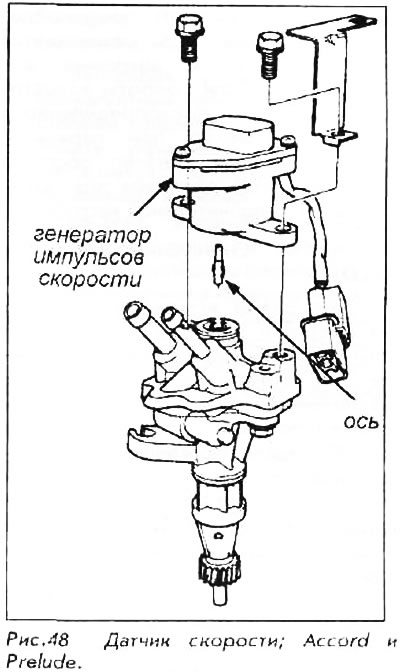
Vehicle Speed Sensor (VSS)
The signal from the vehicle speed sensor is used by the eCu as well as by the cruise control system and/or automatic transmission control units. The Accord and Prelude use an external sensor mounted on top of the speed sensor in the engine bay. The speed sensor is driven by a gear mechanism from the engine and controls the power steering depending on the speed of the vehicle. An electrical impulse generator is mounted on top of this block and connected to it by a small shaft. Movement from the lower block is transferred to the upper one; resulting in an electrical signal sent to the appropriate control units.
Starter Signal
The START position of the ignition key sends a signal to the ECU. During start-up, the ECU increases the amount of fuel injected according to the engine temperature. Fuel supply is gradually reduced when the starter switch is returned to the OFF position.
Signal Generator FR
The ECU receives a signal from the alternator when the system is charging.
Air conditioning signal
The load on the engine increases when the compressor is running; the ECU should increase the idle speed as needed. In some cases, the ECU will limit the operation of the air conditioner by turning it off using the control relay. For example, at wide open throttle or when the engine is cold. If the vehicle has a separate A/C control unit, both units exchange information regarding the status of the system.
Battery Voltage (IGN 1)
12V voltage signal controlled by ignition key in IGN1 position (ON or RUN) enters the ECU.
Automatic Transmission Shift Lever Position Signal
This signal is sent to the ECU via a safety neutral switch. The ECU will not allow the engine to start if the shift lever is not in the N position (neutral) or PARK (stop).
Power Steering Fluid Pressure Sensor
When the power steering fluid pressure exceeds a predetermined level, the ECU is alerted by a pressure sensitive switch. If the idle speed is below a predetermined level, such as when parking, the control unit will increase the engine idle speed to compensate for the extra load.
Power consumption sensor (ELD)
This sensor is only used on the Accord and is located under the hood in the fuse and relay box. It detects the presence of increased current consumption in the system and sends a signal to the ECU.
The ECU will control the idle speed to compensate for the extra load from the headlights and defrosters, defrosters or similar heavy current consumers.
The ELD unit is integrated with the fuse box in which it is housed; if the sensor is out of order, then its replacement with a workable one is carried out together with the fuse box.