
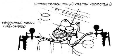
Disconnect the lower solenoid valve vacuum hose from the stabilized vacuum generator and connect the vacuum pump.
Disconnect the upper solenoid valve vacuum hose from the rectifier and connect a pressure gauge.
Disconnect the 2-pin connector near the solenoid valve.
Create a vacuum.
If the solenoid valve does not hold vacuum, then it should be replaced.
If the solenoid valve is holding vacuum, then connect the positive battery terminal to the Green/Black terminal of the 2-pin connector and the negative battery terminal to Black.
Next, create a vacuum.
If the pressure gauge shows no vacuum, the solenoid valve should be replaced.
If the pressure gauge shows a vacuum, then disconnect the contacts of the 2-pin connector from the battery.
If the pressure gauge now shows vacuum, then the solenoid valve should be replaced.
If the pressure gauge shows no vacuum, the vacuum hose must be reconnected.
Next, warm up the engine to operating temperature until the cooling fan turns on.
Measure voltage between Green/Black (+) and Cherny (-) terminals on the main wiring harness while the engine is running at approximately 2500 rpm.
If the voltage fluctuates between 0 and 12 volts, then check the vacuum line for proper connection, cracks, blockage, or hose disconnection.
If the voltage does not change as indicated, then measure the voltage between Green/Black (+) and Cherny (-) contacts and ground while the engine is running at approximately 2500 rpm.
If the voltage fluctuates between 0 and 12 volts, repair the break in the Black wire between the solenoid valve and point G5.
If the voltage does not change as indicated, then check for an open Green / Black wire between the solenoid valve and terminal 29 of the control unit. If the wire is normal, then you should refer to the diagnostics section of the inputs of the control modules.