
Note: See the wiring diagram of the fuel gauge in Ch. «Body electrical equipment».
1. Check the INSTRUMENT UGHT fuse before testing (7.5 A) in the fuse/relay box under the dash.
2. Remove the access panel from the floor.
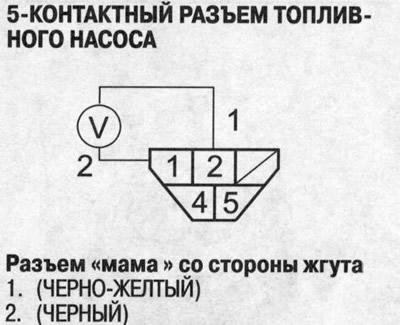
3. Turn the ignition key to the OFF position, then disconnect the 5-pin connector from the fuel pump.
4. Measure the voltage between terminals No. 1 and No. 2 of the 5-pin fuel pump connector when the ignition key is turned to the ON position (II). Should be between 5 and 8 V.
- If the voltage is within the normal range, go to step 6.
- If the voltage is out of specification, check:
- Is there an open in the BLACK-YELLOW or BLACK wire.
- bad grounding (G501).
5. Turn the ignition key to the OFF position.
6. Jumper the #1 and #2 terminals of the 5-pin fuel pump connector, then turn the ignition key to the ON position (II).
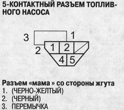
7. Make sure that the arrow of the fuel gauge starts to move towards the mark «F».
- If the pointer needle does not move at all, replace the fuel level indicator.
- If the fuel gauge is OK, check the fuel gauge sensor.
Note:
- Before the arrow reaches the mark «F» on the gauge scale, turn the ignition key to the OFF position. Failure to do so may damage the pointer.
- The fuel level gauge is coil type, so the fuel level is displayed continuously even when the ignition key is turned to the OFF position and the pointer moves slower than that of the bimetal type gauge.