
Upper arm
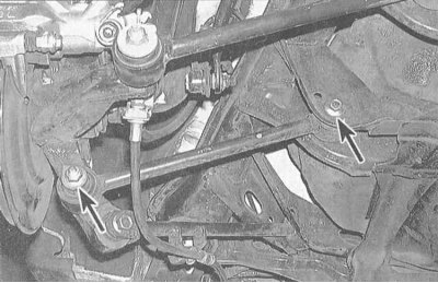
1. Give a nut of a through bolt of fastening of the top suspension arm to stupny assembly. Also remove the ball stud nut of the arm support. Using a 2-jaw puller, separate the lever from the hub assembly.
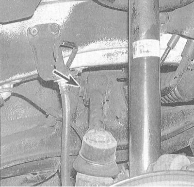
2. Turn out bolts of fastening of a basic arm of a brake hose, take the brake line aside.
3. On models equipped with ABS, remove the wheel sensor to avoid accidental damage to its wiring.
4. Remove the bolt securing the inner end of the upper arm to the chassis.
5. Remove the upper arm. Check the condition of the rubber bushings of the lever, evaluate the slack fit and the degree of wear of the ball joint. Replace worn and damaged components.
6. Installation is carried out in the reverse order. Make sure all fasteners are tightened to the correct torque. Remember to secure the ball stud castle nut with a new cotter pin (see Note to paragraph 1 of Section Removal and installation of a rotary fist).
Lower arm
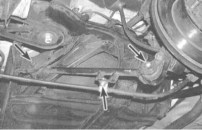
1. Give a nut of a bolt of fastening of the bottom lever to stupny assembly.
2. Turn out an axial bolt of fastening of the internal end of the lower arm to the chassis.
3. Remove the lower arm assembly.
4. Check up a condition of rubber plugs, in case of need replace the lever.
5. Installation is carried out in the reverse order. Make sure all fasteners are tightened to the correct torque.
Front trailing arm
1. Disconnect the parking brake cable support bracket from the trailing arm.
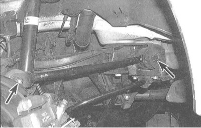
2. Turn out a bolt of fastening of the trailing arm to stubny assembly.
3. Turn out a bolt of fastening of the trailing arm to the chassis.
4. Remove the front trailing arm.
5. Check up a condition of the plug established in a forward part of the lever. In case of defects, replace the lever.
6. Installation is carried out in the reverse order. Make sure all fasteners are tightened to the correct torque.
Trailing arm
1. Turn out a bolt of fastening of the trailing arm to stupny assembly.
2. Turn out a bolt of fastening of the lever to the chassis.
3. Remove the lever.
4. Check up a condition of the plug established from the internal end of the lever. In case of defects, replace the lever.
5. Installation is carried out in the reverse order. Make sure all fasteners are tightened to the correct torque.
Control lever
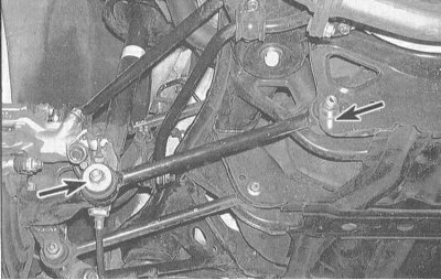
1. Give back ha (see accompanying illustration).
2. Mark the position of the adjusting cam in relation to the support bracket of the inner end of the arm. Give a nut, and take a bolt of fastening of the lever to the chassis.
3. Remove the lever.
4. Check up a condition of rubber plugs of the lever. In case of defects, replace the lever.
5. Installation is carried out in the reverse order. Follow the correct alignment of the landing marking applied during dismantling (see paragraph 2). Tighten all fasteners to the required torque.