
- Before removing the fuel supply hose, relieve the fuel pressure (see chapter Engine power supply system).
- Take fire safety measures.
- Do not open the radiator cap on a hot engine, as the coolant is under pressure and may spill out. After the coolant has cooled, cover the cap with a rag and open it slowly.
- To avoid damaging the paintwork, cover the surfaces with film.
- To avoid thermal deformation, remove the cylinder head on a cold engine (below 38°C).
- There are metal components on the cylinder head gasket, so do not bend the gasket.
- Be careful not to damage the contact surface of the block and cylinder head gasket.
- During disassembly, replace all O-rings and gaskets with new ones.
1. Disconnect the cables from the battery terminals.
First, disconnect the cable from the negative terminal.
- Before connecting the cables, clean the contact surfaces of the terminals with sandpaper and apply grease to them.
2. Drain the coolant (see below).
Be careful, the coolant is very hot.
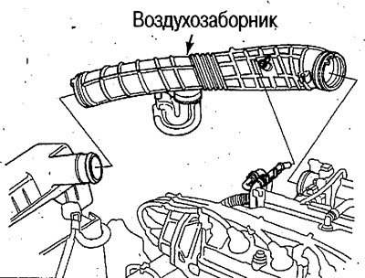
3. Remove the air intake.
4. Loosen the mounting and locking bolts, remove the pump belt and the steering pump.
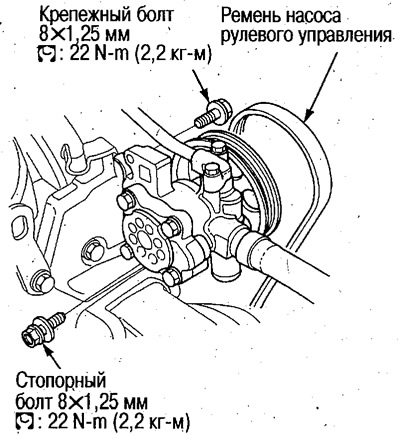
- Do not disconnect the pump hoses.
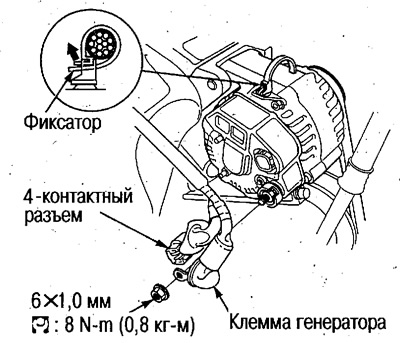
5. Disconnect the terminal and the 4-pin connector of the generator.
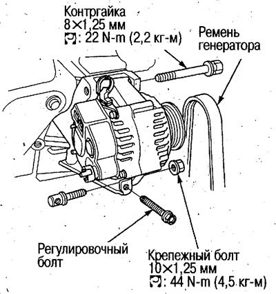
6. Loosen the mounting bolt, lock nut and adjusting bolt, remove the alternator belt and alternator.
7. Remove the generator bracket (see below).
8. Relieve the fuel pressure (see chapter Engine power supply system).
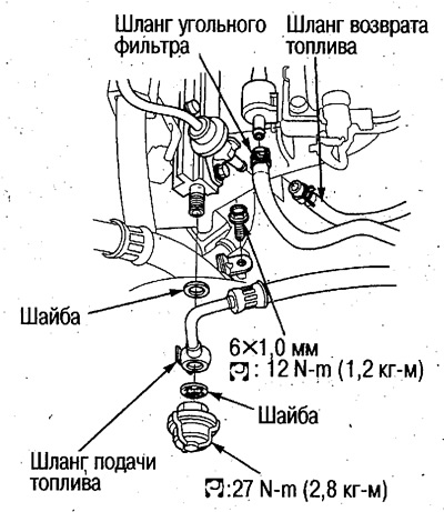
9. Disconnect the carbon filter, fuel supply and return hoses, remove the clamps of the power steering pump hoses.
10. Disconnect the throttle cable.
Attention:
- Do not bend the cable during removal and installation.
- If the cable is kinked, replace it.
- Mark the position of the adjusting nut.
 |
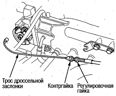 |
- After installation, perform adjustment (see chapter Engine Management System).
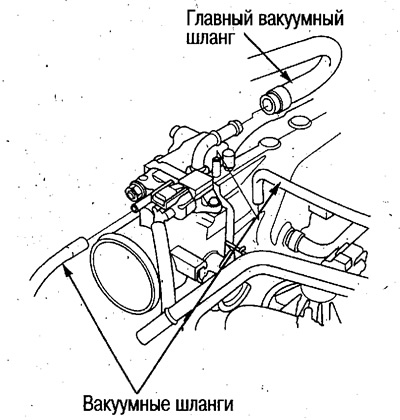
11. Disconnect the vacuum hoses and the main vacuum hose.
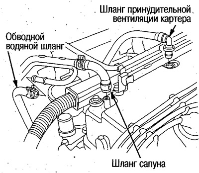
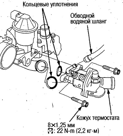
12. Disconnect the positive crankcase ventilation hose and the bypass water hose.
13. Disconnect all engine electrical wiring connectors, remove all clamps and stands around the cylinder head, throttle body and intake manifold:
- 4 fuel injector connectors
- Intake Air Temperature Sensor Connector
- Intake Air Pressure Sensor Connector
- Coolant Temperature Sensor Connector
- Coolant Temperature Gauge Sensor Connector
- Open Throttle Position Sensor Connector
- Air swirl control valve connector
- VTEC solenoid valve connector
- Ignition distributor connector
- TDC/Crankshaft Sensor Connector
- Oxygen sensor connector
- EGR valve connector
14. Remove the ignition distributor.
15. Remove the stopper, disconnect the ground cable and remove the upper bracket.
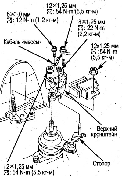
- Support the engine oil pan with a jack, placing a wooden block underneath.
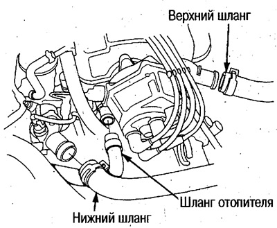
16. Disconnect the upper and lower hoses and the heater hose.
17. Disconnect the bypass water hose and remove the thermostat housing.
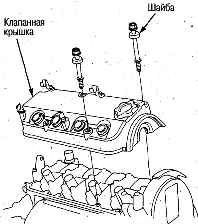
18. Remove the valve cover.
19. Remove the timing belts and balance shafts (see above).
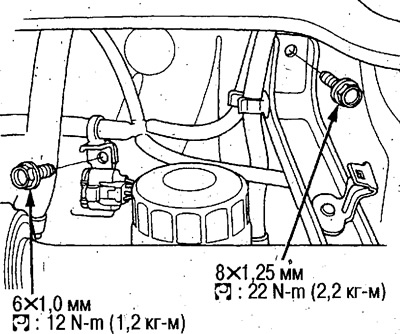
20. Remove the electrical wiring stand and unscrew the bolt connecting the stand to the intake manifold.
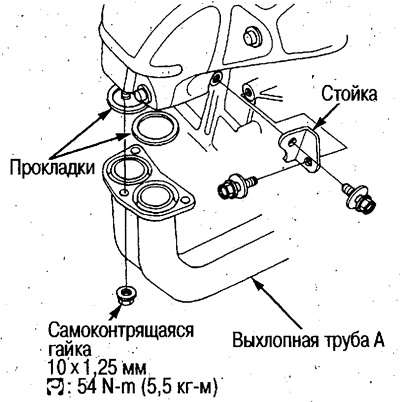
21. Remove the exhaust manifold stand and unscrew the self-locking nut.
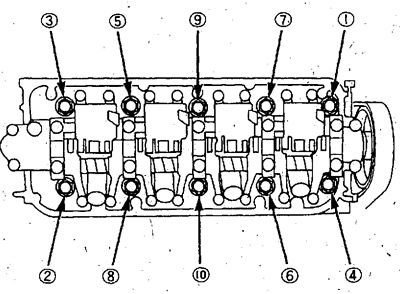
22. Remove the cylinder head.
Caution: Do not loosen the cylinder head bolts in one go, but do so in several steps in the order shown in the illustration.
Sequence for loosening cylinder head bolts:
Checking the cylinder head bolts
1. Measure the bolt diameter at the two locations shown in the figure.
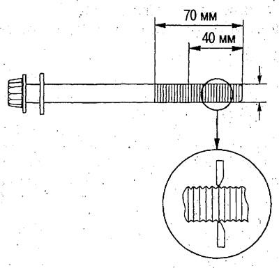
Take measurements on all cylinder head bolts.
- Maximum diameter: 11.3 mm
2. If the diameter is less than the limit, replace the bolt.
(Original article on the website hondabook.ru)