Testing at the input of the control unit (without remote door locking system)
1. Remove the bottom pocket from the driver's side (see ch. «Body»).
2. Disconnect the 6-pin connector from the control box.
3. Check the connector and socket contacts to make sure they make good contact.
- If the contacts are bent, loose, or rusted, repair and recheck the system.
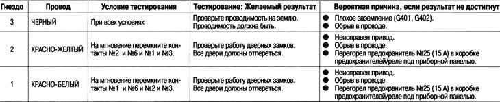
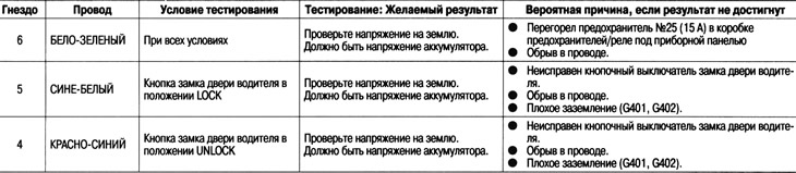
- If the pins appear to be OK, perform the following checks on the connector.
- If any of the checks indicate a problem, find and correct the cause, then recheck the system.
- If testing at the input of the block shows the norm, the control unit must be faulty, replace it.
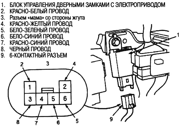
Disconnect the 6-pin connector from the power door lock control module
Connect the 6-pin connector to the power door lock control module
Testing at the input of the control unit (with remote door locking system)
1. Remove the bottom pocket from the driver's side (see ch. «Body»),
2. Disconnect the 14-pin connector from the control box.
3. Check the connector and socket contacts to make sure they make good contact.
- If the contacts are bent, loose, or rusted, repair and recheck the system.
- If the pins appear to be OK, perform the following checks on the connector.
- If any of the checks point to non-
- serviceability, find and eliminate the cause, then recheck the system.
- If testing at the input of the block shows the norm, the control unit must be faulty, replace it.
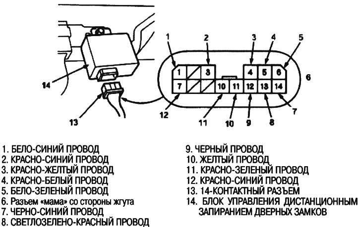
Disconnect the 14-pin connector from the remote door lock control unit
Connect the 14-pin connector to the remote door lock control unit
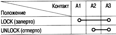
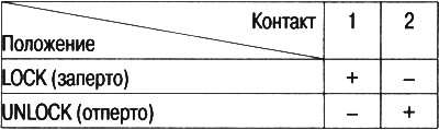
Testing the driver's door lock button switch
1. Remove the door panel from the driver's side (see ch. «Body»).
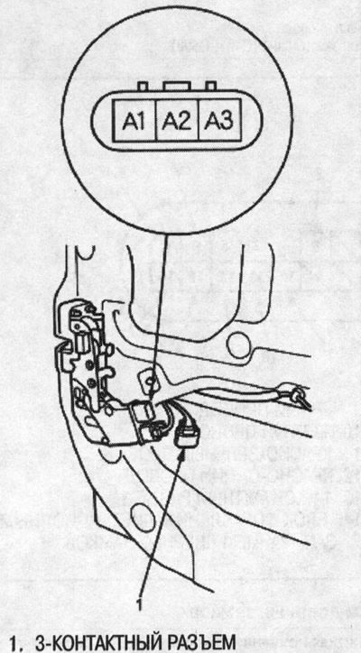
2. Disconnect the 3-pin connector from the pushbutton (without remote door locking system) or drive (with remote door locking system).
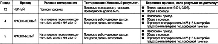
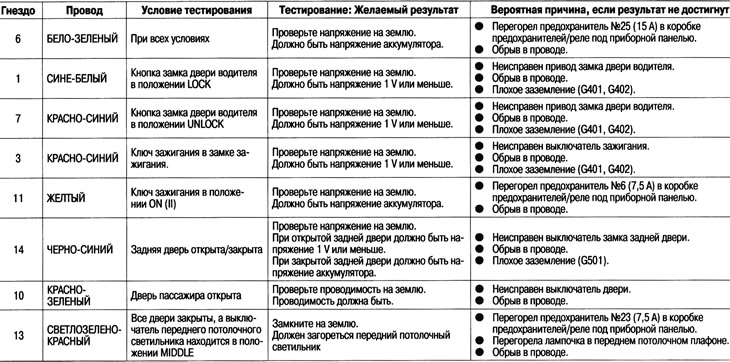
3. Check the presence of continuity between the contacts in all positions of the switch in accordance with the table.
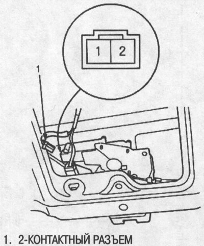
Testing the driver's door lock actuator (with remote door locking system)
1. Remove the door panel from the driver's side.
2. Disconnect the 2-pin connector from the drive.
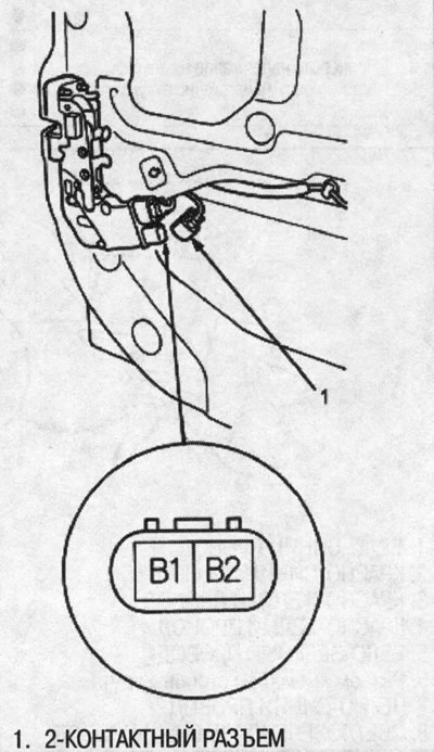
Warning! Apply battery voltage only briefly to avoid damage to the drive.
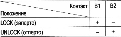
3. Check the operation of the drive by applying power and ground according to the table.
Passenger Door Lock Actuator Test
1. Remove the door panel on the passenger side.
2. Disconnect the 2-pin connector from the drive.
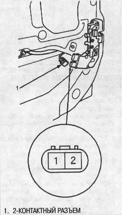
Warning! Apply battery voltage only briefly to avoid damage to the drive.
3. Check the operation of the drive by applying power and ground according to the table.
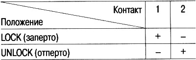
Testing the tailgate lock actuator
1. Remove the decorative panel from a back door.
2. Disconnect the 2-pin connector from the drive.
Warning! Apply battery voltage only briefly to avoid damage to the drive.
3. Check the operation of the drive by applying power and ground according to the table.
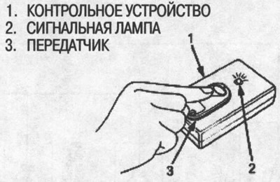
Transmitter testing
Note:
- If the doors are unlocked and locked using the transmitter, but the LED on the transmitter does not light up, then the LED is faulty; replace the transmitter.
- If any door is open, the doors cannot be locked or unlocked using the transmitter.
- If you have unlocked the doors with the transmitter but have not opened any of the doors within 30 seconds, the doors will lock automatically again.
- If the ignition key is inserted into the ignition switch, the doors cannot be locked or unlocked using the transmitter.
1. With remote door lock control (07MAJ-SP00300):
Put the transmitter on the control device and press the button on the transmitter.
- If the warning light does not come on, check:
- Is the battery dead.
- Is the transmitter correct?
- If the warning light comes on, the transmitter is OK.
Note:
- After replacing the battery in the transmitter, point the transmitter at the receiver and press the transmitter button six times.
- On the sixth press, check that the sound of the door lock actuators is heard.
Transmitter Programming
Entering transmitter codes into memory:
The codes of up to three transmitters can be read into the remote control receiver's memory. When entering the fourth code, the code entered first is erased.
Note: It is important to observe the time intervals between the execution of individual operations.
1. Turn the ignition key to the ON position (II).
2. Within 1-4 seconds, press the lock or unlock button on the transmitter while aiming the transmitter at the receiver (Control block).
3. Within 1-4 seconds, turn the ignition key to the OFF position.
4. Within 1-4 seconds, turn the ignition key to the ON position (II).
5. Within 1-4 seconds, press the lock or unlock button on the transmitter while aiming the transmitter at the receiver (Control block).
6. Within 1-4 seconds, turn the ignition key to the OFF position.
7. Within 1-4 seconds, turn the ignition key to the ON position (II).
8. Within 1-4 seconds, press the lock or unlock button on the transmitter while aiming the transmitter at the receiver (Control block).
9. Within 1-4 seconds, turn the ignition key to the OFF position.
10. Within 1-4 seconds, turn the ignition key to the ON position (II).
11. Within 1-4 seconds, press the lock or unlock button on the transmitter while aiming the transmitter at the receiver (Control block).
12. Check that you can hear the sound of operation of the door lock actuators. Within 1-4 seconds, press the lock or unlock button on the transmitter again.
13. Aim the transmitter for 15 seconds (maximum three), whose codes you want to memorize, on the receiver and press the lock or unlock buttons.
After entering the code of each transmitter into memory, check that the sound of operation of the door lock actuators is heard.
14. Turn the ignition key to the OFF position and remove the key.
15. Check for proper operation with the new codes.
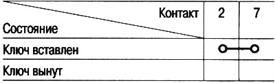
Ignition switch test
1. Remove the bottom pocket from the driver's side (see ch. «Body»).
2. Disconnect the 7-pin connector from the under-dash fuse/relay box.
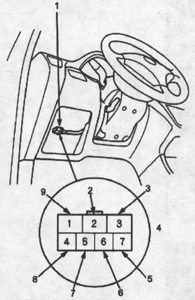
1. 7-pin connector; 2. white-blue wire; 3. white wire; 4. socket «Mother» from the side of the tourniquet; 5. white-blue wire; 6. black and white wire; 7. yellow wire; 8. black and yellow wire; 9. black and white wire
3. Check for continuity between pins #2 and #7 under each condition according to the table.