
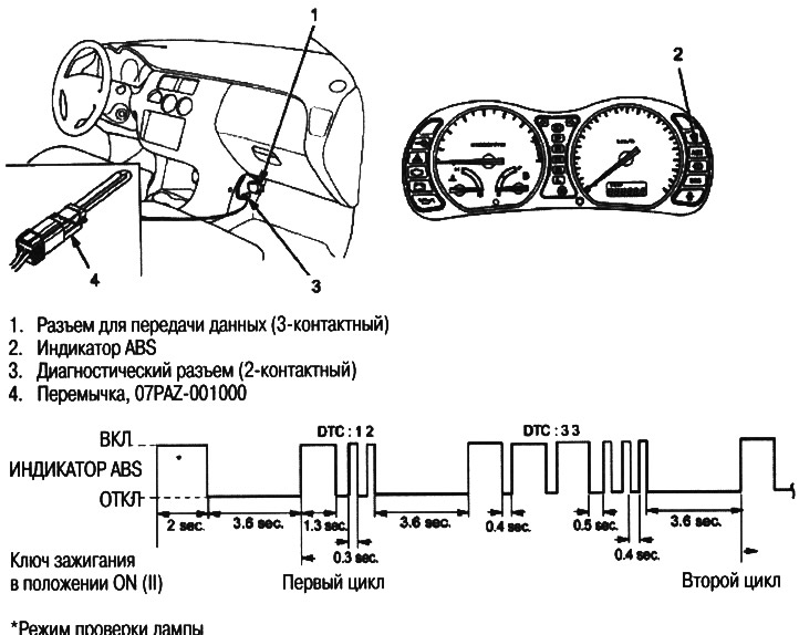
Indication of the diagnostic trouble code (DTC)
Note: This operation can also be performed using the Honda PGM Tester.
1. Jumper the diagnostic connector (2 pin), located on the center console on the passenger side.
2. Turn the ignition key to the ON position (II).
Note: Do not depress the brake pedal when turning the ignition key.
3. Write down the number of flashes (blinking) ABS indicator, which indicates the DTC code.
4. Turn the ignition key to the OFF position and remove the jumper from the diagnostic socket.
Note: If the jumper is left in the diagnostic socket, the malfunction indicator lamp will be on after the engine is started (MIL).
5. Clear the DTC.
Conditions under which the DTC is set
- The car is worth it.
- The diagnostic connector is shorted by a jumper before turning the ignition key to the ON position (II).
- The brake pedal is released.
- The diagnostic socket remains shorted by a jumper during this procedure.
The DTC is stopped and the ABS control unit executes its programmed function if at least one of the following conditions is met:
- The car is not worth it.
- The ABS control unit receives a standard signal from the Honda PGM Tester.
- The jumper was removed from the diagnostic socket when performing this procedure.
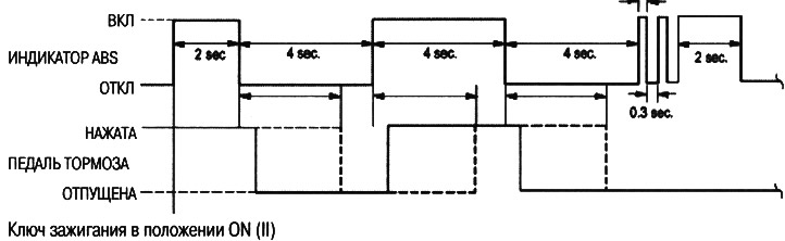
Erasing diagnostic trouble codes (DTC)
Note: This operation can also be performed using the Honda PGM Tester.
1. Jumper the diagnostic connector (2 pin), located on the center console on the passenger side.
2. Press the brake pedal.
3. Turn the ignition key to the ON position (II), while keeping the brake pedal depressed. The ABS indicator will turn off after two seconds.
4. After the ABS indicator goes out, release the brake pedal. The indicator will light up after four seconds.
5. After the indicator lights up, depress the brake pedal again. (The indicator will turn off again after four seconds. Brake pedal still pressed).
6. After the indicator goes out, release the brake pedal again.
7. After four seconds, the indicator will flash twice for 0.3 seconds and the DTC will be cleared.
8. Check the DTC indication and make sure it cleared.
Note: Always follow these steps. If you remove the jumper from the diagnostic connector and do not depress the brake pedal as indicated by the indicator, the DTC will not be cleared.
Conditions under which the DTC is cleared
- The car is worth it.
- The diagnostic connector is shorted by a jumper before turning the ignition key to the ON position (II).
- The brake pedal is depressed before turning the ignition key to the ON position (II).
- The diagnostic socket remains shorted by a jumper during this procedure.
Clearing the DTC stops and the ABS control unit executes its programmed function if at least one of the following conditions is met:
- The car is not worth it.
- The jumper was removed from the diagnostic socket when performing this procedure.
- The ABS control unit receives a standard signal from the Honda PGM Tester.
- The brake pedal is not depressed in accordance with the indication of the indicator,
- Clearing the DTC is completed.
Troubleshooting Index
Note: This operation can also be performed using the Honda PGM Tester.
| DTC code | ABS indicator | Brake indicator | Diagnosis/Symptom | Detection time | ||||
| Primary diagnosis | Without ABS control | with ABS control | When a warning signal is issued | Fault location | ||||
| No code | - | Lit (ON) | Brake indicator does not turn off | - | - | - | - | |
| No code | Does not burn (OFF) | - | ABS indicator does not light up | - | - | - | - | |
| No code | Lit (ON) | - | ABS indicator does not turn off | - | - | - | - | |
| 11 | Lit (ON) *1 | Lit (ON) *3 | wheel sensor (open/short circuit to ground/short with power supply) | O | O | O | O | Front right side (FR) |
| 13 | Lit (ON) *1 | Lit (ON) *3 | wheel sensor (open/short circuit to ground/short with power supply) | O | O | O | O | Front left side (FL) |
| 15 | Lit (ON) *1 | Lit (ON) *3 | wheel sensor (open/short circuit to ground/short with power supply) | O | O | O | O | Rear right side (RR) |
| 17 | Lit (ON) *1 | Lit (ON) *3 | wheel sensor (open/short circuit to ground/short with power supply) | O | O | O | O | Rear left side (RL) |
| 12 | Lit (ON) *1 | Lit (ON) *3 | Wheel sensor/pulse generator (chipped toothed ring/electrical interference) | O | O | O | Front right side (FR) | |
| 14 | Lit (ON) *1 | Lit (ON) *3 | Wheel sensor/pulse generator (chipped toothed ring/electrical interference) | O | O | O | Front left side (FL) | |
| 16 | Lit (ON) *1 | Lit (ON) *3 | Wheel sensor/pulse generator (chipped toothed ring/electrical interference) | O | O | O | Rear right side (RR) | |
| 18 | Lit (ON) *1 | Lit (ON) *3 *3 | Wheel sensor/pulse generator (chipped toothed ring/electrical interference) | O | O | O | Rear left side (RL) | |
| 31 | Lit (ON) | Lit (ON) | Solenoid (open/short circuit to ground/short with power supply/stick) | O | O | O | Front right - inlet (FR-IN) | |
| 32 | Lit (ON) | Lit (ON) | Solenoid (open/short circuit to ground/short with power supply/sticking) | O | O | O | Front right-outlet (FR-OUT) | |
| 33 | Lit (ON) | Lit (ON) | Solenoid (open/short circuit to ground/short with power supply/sticking) | O | O | O | Front Left - Intake (FL-IN) | |
| 34 | Lit (ON) | Lit (ON) | Solenoid (open/short circuit to ground/short with power supply/sticking) | O | O | O | Front left-exhaust (FL-OUT) | |
| 35 | Lit (ON) | Lit (ON) | Solenoid (open/short circuit to ground/short with power supply/sticking) | O | O | O | Rear right - inlet (RR-IN) | |
| 36 | Lit (ON) | Lit (ON) | Solenoid (open/short circuit to ground/short with power supply/sticking) | O | O | O | Rear right-outlet (RR-OUT) | |
| 37 | Lit (ON) | Lit (ON) | Solenoid (open/short circuit to ground/short with power supply/sticking) | O | O | O | Rear left - inlet (RL-IN) | |
| 38 | Lit (ON) | Lit (ON) | Solenoid (open/short circuit to ground/short with power supply/sticking) | O | O | O | Rear left-exhaust (RL-OUT) | |
| 51 | Lit (ON) | Does not burn (OFF) | electric motor | O | O | |||
| 52 | Lit (ON) | went out (OFF) | Electric motor stuck in the off state (OFF) | O | O | |||
| 53 | Lit (ON) | went out (OFF) | Electric motor stuck on (ON) | O | ||||
| 54 *4 | Lit (ON) | Lit (ON) | Motor relay stuck open (OFF) | O | O | O | ||
| 61 | Lit (ON) *2 | Lit (ON) | Ignition voltage (high voltage/low voltage) | O | O | O | O | |
| 81 | Lit (ON) | Lit (ON) | Hardware failure | O | O | O | O | |
| 81 *5 | Lit (ON) | Lit (ON) | Interference detection | O | O | O | ||
*1: If DTCs 11 to 18 are detected when the vehicle was last driven (wheel sensor codes), the ABS indicator will stay on until the ignition key is turned to the ON position (II) and the control unit will not confirm that the wheel sensors are OK.
*2: The ABS indicator goes out when the ignition voltage returns to normal.
*3: The brake system indicator lights up when the ABS control unit detects a malfunction on more than one wheel.
*4: This code is issued only when using the Honda PGM Tester.
*5: Communication mode failure code for Honda PGM Tester is 82.