
Contents: Removal ⇊ Installation ⇊
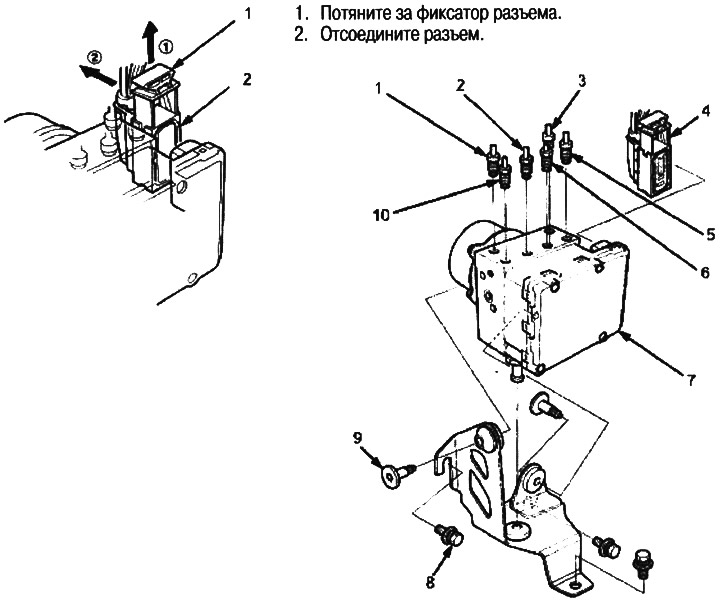
1. CONNECTOR LOCKER
2. ABS CONTROL UNIT CONNECTOR
1. To the secondary piston side of the master cylinder
2. To the right rear wheel slave cylinder
3. To the primary piston side of the master cylinder
4. ABS CONTROL UNIT CONNECTOR
5. To the right front wheel support
6. To the left rear wheel slave cylinder
7. MODULATOR ASSEMBLY (CONTROL UNIT / ABS MODULATOR UNIT)
8. BOLT 8 mm, 22 Nm (2.2 kgf/m)
9. TORX BOLT, 9.8 Nm (1.0 kgf/m)
10. To the left front wheel support
Note:
- Do not spill brake fluid on your car as it may damage the paintwork; if liquid does spill, wash it off immediately with water.
- When removing and installing, do not damage or deform the brake pipes.
- To prevent brake fluid from leaking, plug or cover the ends of the hoses and fittings with napkins or similar material.
Removal
1. Disconnect the connector from the ABS control unit as shown in the figure.
2. Disconnect the brake pipes, then remove the modulator assembly.
Installation
1. Install the modulator assembly, then connect the brake pipes.
2. Connect the connector to the ABS control unit in the reverse order of disconnection.
3. Bleed the brake system, starting with the front wheels.
4. Start the engine and make sure the ABS indicator goes out.
5. Perform a road test and make sure the ABS indicator does not come on.
(Article source on the website: www.hondabook.ru)