
Warning! Remember that dust generated during wear of the clutch slave disk friction linings may contain asbestos, which is harmful to health. Do not blow off dust with compressed air and try not to inhale it. Do not use petroleum-based solvents to wipe clutch components - use only special brake cleaners or pure methyl alcohol. Place used rags in a hermetically sealed container.
Removal
1. In order to provide access to the clutch assembly, the gearbox is usually removed, leaving the engine in the car. If the engine has already been removed for general or major repairs, the condition of the clutch components must be checked without fail. Considering the relatively low cost of the parts and the fairly large amount of mechanical work required to provide access to the clutch assembly, it makes sense to replace the latter regardless of the condition of its components. Below is a description of the procedure for removing the clutch without removing the engine from the car.
2. Remove the gearbox (see Section 5-speed manual transmission (MT)). Support the engine with a jack or hang it from above on a winch (preferably the latter). If using a jack, do not forget to place a wooden block between its head and the oil pan to distribute the load.
Attention! The oil intake of the oil pump is located very close to the bottom of the oil pan and can easily be damaged if the latter is deformed.
3. The clutch release fork and release bearing can be left in their standard locations in the transmission housing.
4. To prevent the driven disk from falling out when removing the basket, insert a tool designed for clutch centering into its hub.
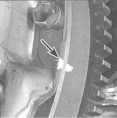
5. Carefully inspect the flywheel and clutch basket assembly surfaces for markings (usually in the form of white letters X or O). If you cannot find the markings, apply them yourself, clearly marking the position of the basket relative to the flywheel.
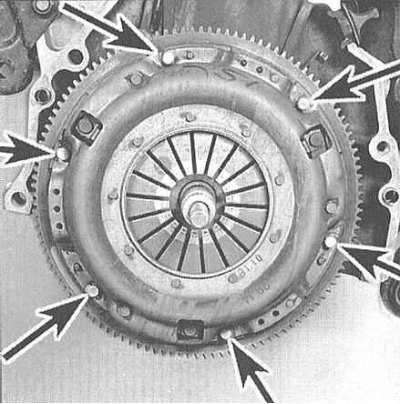
6. Working diagonally, loosen the clutch basket-to-flywheel mounting bolts evenly in several steps, completely relieving the diaphragm spring. While securely supporting the clutch assembly, remove the bolts completely, then separate the basket from the flywheel and remove the entire assembly from the vehicle.
Examination
1. Most often, the malfunction of the clutch is associated with wear of the friction linings of the driven disk. However, it is necessary to carefully examine the condition of all other components of the assembly.
2. Examine the flywheel working surface for cracks, traces of overheating, grooves and other damage. Minor defects can be eliminated by turning in a car service workshop (turning is recommended regardless of the surface condition). A description of the flywheel removal and installation procedures is given in the corresponding Section of the Chapter Engine.
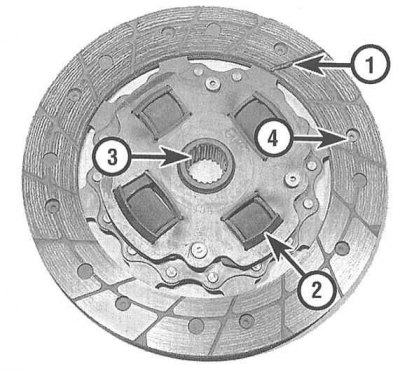
3. Assess the degree of wear of the friction linings of the driven clutch disc. The surface of the linings should rise above the rivet heads by at least 1.6 mm. Make sure that all rivets are tightly seated, check the torsion springs/dampers for cracks, signs of deformation and other mechanical damage. As mentioned above, it is reasonable to replace the clutch components every time the assembly is dismantled, so pay attention to the slightest errors.
4. The release bearing is always replaced together with the driven disk (see Section Removal, condition check and installation of the release bearing and clutch release fork).
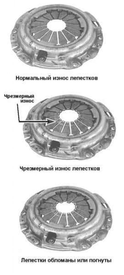
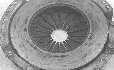
5. Assess the condition of the machined surfaces and petals of the diaphragm spring of the pressure plate. If defects are found, replace the basket assembly. Traces of light polishing can be removed using fine-grained sandpaper. A restored clutch assembly can always be purchased on an exchange basis through Honda service stations.
Installation
1. Before installation, wipe the machined surfaces of the flywheel and pressure plate with a rag soaked in acetone. It is extremely important to achieve complete degreasing of the working surfaces of the components, as well as the friction linings of the driven disk. Touch the components only with clean hands.
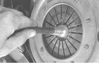
2. Press the basket assembly (with the driven disc alignment tool inserted and secured) onto the flywheel. Make sure that the side of the clutch disc marked with the appropriate marking (like "flywheel side") faces the flywheel. If there is no marking, remember that the driven disc is always mounted with torsion springs/dampers to the gearbox.
3. Hand tighten the assembly-to-flywheel mounting bolts.
4. Center the clutch assembly components. The special tool is passed through the driven disk hub and inserted into the pocket in the end of the crankshaft journal. To align the components, move the tool in different directions in the vertical and horizontal planes. Acting diagonally, tighten the assembly mounting bolts tightly in several steps, then tighten them with the required force. Remove the clutch centering tool.
5. Pack the inner groove of the release bearing with high-melting grease (see Section Removal, condition check and installation of the release bearing and clutch release fork). Also lubricate the contact surfaces of the clutch release lever and the gearbox input shaft bearing holder.
6. Install the release bearing (see Section Removal, condition check and installation of the release bearing and clutch release fork).
7. Install the gearbox and all components removed for access.