
Warning! Avoid touching the impeller blades with your hands, tools and clothing. To avoid personal injury or property damage, do not start the engine with a defective fan. Do not attempt to repair broken impeller blades - change it as an assembly!
Examination
Note. On all models equipped with A/C, two fans are provided - one for blowing the radiator of the engine cooling system, and the second for blowing the condenser of the air conditioning system. The procedures described below apply equally to both fans.
1. For check of serviceability of functioning of the electric motor of a drive of the fan disconnect a socket of its conducting. Now, using the fused jumper wire, connect the fan directly to the battery. If the impeller does not turn, replace the electric motor.
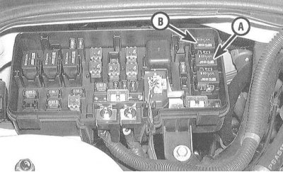
2. If the motor is OK, check the condition of the cooling fan fuses (the fuses are located in the mounting block located on the left under the instrument panel, on V6 models check fuses #3 and #6, on 4-cylinder - #4), sensor (ov) -switch (to her) fan (ov), cooling fan relay, A/C fan relay (mounting block in the engine compartment) and connecting wiring of the corresponding circuit.
Attention! on 4-cylinder models there is only one sensor-switch of the cooling fan, on V6 models there are two such sensors-switches ("A" And "IN").
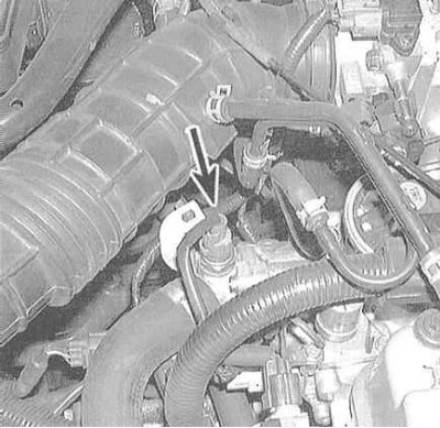
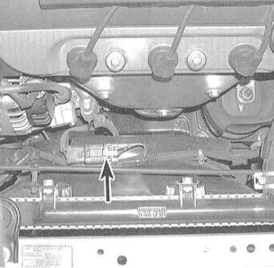
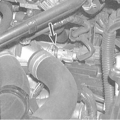
3. For check of serviceability of functioning of any of gauges-switches of the fan of system of cooling, disconnect a socket of its electroconducting. Start the engine and use an ohmmeter to check that there is no continuity between the sensor-switch terminals when the engine is cold (below 88°C there should be no conductivity). The closing of the sensor-switch should occur after the coolant has warmed up to a temperature above 92÷96°C. The closing temperature of the sensor-switch of the K / V capacitor is 108°С. In case of violation of the described dependence of the presence of conductivity, replace the faulty sensor-switch. The opening of each of the sensors-switches should occur at a temperature of 3÷8 degrees below the temperature of their closing.
 |  |
Attention! Do not leave the engine running with the switches disconnected longer than necessary to carry out the described checks. Do not delay with the restoration of the original wiring, then, after allowing the fan to rotate a little, turn off the ignition.
4. On 4-cylinder models, there is only one thermal sensor-switch that controls the operation of the fans of both systems (refrigeration and air conditioning). There are two such switches on V6 models - one for each of the systems.
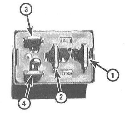
5. To test the fan relay, remove the appropriate relay from its socket in the mounting block, connect terminal 3 to the battery, and ground terminal 4. A good relay should close, creating continuity between terminals 1 and 2, which should disappear when the power is turned off.
Checking the Fan Control Module
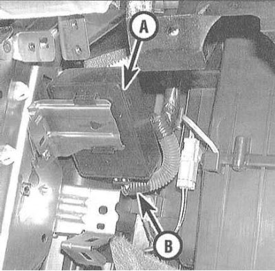
1. On V6 models, the operation of the cooling fan is controlled by a dedicated electronic module located under the front passenger's knee brace. Remove the stop (see chapter Body). Probe the terminals of each of the wires on the reverse side of the module connector with a sharp probe at two positions of the ignition switch (ON and OFF). Be careful - try not to pierce the insulation.
2. Make sure there is continuity between the black wire terminal and ground. If there is no continuity, check the continuity of the ground loop.
3. Check for battery voltage at the terminals of the following wires: white, black-yellow-1, black-yellow-2, yellow-white and yellow. If there is no voltage, check the condition of the appropriate fuses in both mounting blocks (under the instrument panel and in the engine compartment).
4. Switch on the ignition again, restoring the original wiring connection. Ground the green wire terminal to ground. If the fans do not work, check the green, yellow and yellow-white wires for an open
5. Measure the voltage at the white/green wire terminal. The required value when the engine temperature is below 107°C is 11÷12 V, - otherwise, check for a short circuit to the chassis ground, evaluate the condition of the control module and the temperature-sensitive sensor-switch.
6. Before testing a new module, disconnect both fan relays and check for continuity between the yellow/yellow-white wire terminal and ground (set the measuring range on the ohmmeter to 20 kΩ). If conduction occurs, the new module will also fail when switched on.
Replacement
Note. The procedures described below apply equally to both fans.
1. Disconnect the negative cable from the battery.
Note. If the stereo system installed in the car is equipped with a security code, before disconnecting the battery, make sure that you have the correct combination to activate the audio system!
2. Apply the parking brake and chock the rear wheels of the vehicle. Jack up the front of the car and place it on jack stands. If equipped, remove the lower radiator splash screen.
3. Inserting a small screwdriver into the connector, release the locking tab and disconnect the fan wiring.
Note. On models equipped with a speed control system, release the tempostat drive cable from the two plastic clips on top of the fan shrouds.
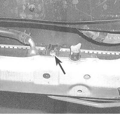
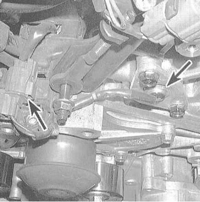
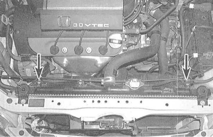
4. On the air conditioning fan assembly, remove the bottom mounting bolt
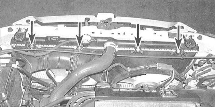
5. Unscrew the fan from the top of the radiator.
6. Carefully remove the fan from the engine compartment.
Attention! With the appropriate configuration, it is necessary to take aside the tempostat drive cable released from the clamps.
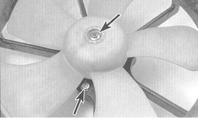
7. To remove the impeller from the motor shaft, release the central nut.
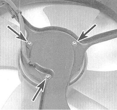
8. Remove the mounting screws to remove the drive motor from the fan shroud.
9. Installation is carried out in the reverse order.