
Contents: 1984-85 Accord, 1984-86 Prelude,…⇊ For assembly: ⇊ 1986-89 Accord, 1987 Prelude fuel…⇊ To install: ⇊ 1990-91 Accord, 1991 Prelude ⇊
1984-85 Accord, 1984-86 Prelude, 1987 Prelude, carbureted
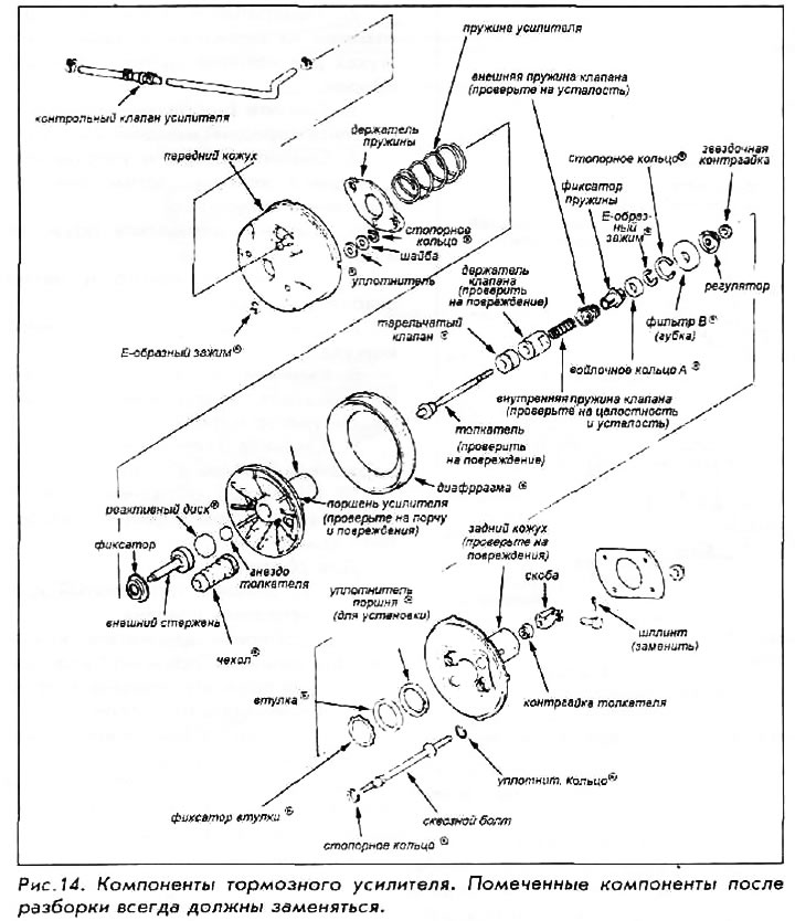
1. Remove the brake booster.
2. Scratch alignment marks on the front and rear covers to aid in reassembly later.
3. Remove the E-clips and separate the front and rear covers.
4. Remove the washers and seals from the rear housing, then remove the retaining ring.
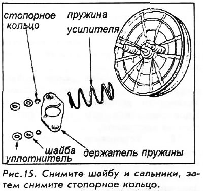
5. Remove the spring retainer and booster spring.
6. Remove the retainer and through bolt boots.
7. Remove the diaphragm from the rear housing.
8. Remove the eye, pushrod locknut, star locknut, regulator and filter.
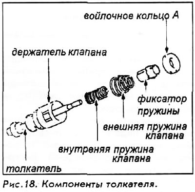
9. Remove the retaining ring and valve retainer assembly.
10. Remove the E-clip from the valve holder assembly and disassemble the components.
For assembly:
11. Install the poppet valve onto the valve holder.
12. Assemble the valve retainer, inner valve spring, outer valve spring and spring retainer onto the tappet.
13. Install the felt ring with the E-clip.
14. Install the diaphragm onto the booster piston. Align the keys with the slots in the piston.
15. Coat the inside and outside surfaces of the piston tube with silicone grease. Insert the valve retainer assembly into the piston. Install the retaining ring.
16. Install the anti-foam filter on the end of the pusher; screw the adjuster and locknut onto the shaft, but do not tighten.
17. Use silicone grease to seal the piston. Install the seal on the housing. Make sure that the edges of the seal do not protrude.
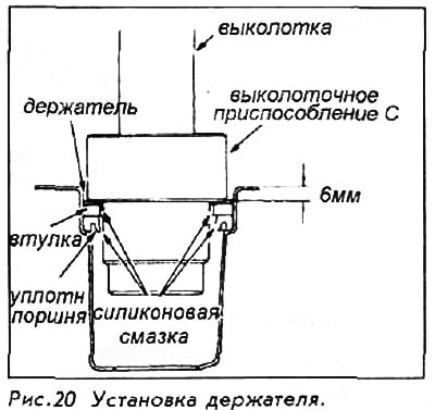
18. Install the piston seal and bushing into the rear housing. Use a suitable tool to carefully position the retainer 6 mm below the edge of the rear housing. If the retainer is moved more than 6 mm, the piston seal will be damaged.
19. Install both through bolts using the O-rings and snap rings.
20. Align the booster piston key with the slot in the rear housing and attach the piston.
21. Install the covers onto the through bolts.
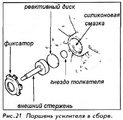
22. Lubricate the booster piston bore with silicone grease and install the pushrod seat, reaction disk, outer rod and retainer.
23. Install the booster spring.
24. Compress the booster spring, install the spring retainer and install the snap rings on the through bolts.
25. Install washers and seals on the through bolts. Assemble the front and rear housings, aligning them with the marks made earlier. Press the front housing down and install the E-clips.
26. Adjust the tappet clearance. See separate procedure in this Chapter.
1986-89 Accord, 1987 Prelude fuel injected, 1988-90 Prelude
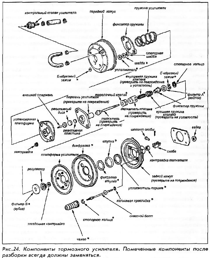
1. Remove the brake booster.
2. Scratch marks on the front and rear covers to facilitate subsequent assembly.
3. Remove the E-clips and separate the front and rear covers.
4. Remove the seals and washers from the spring retainer; remove the retaining ring.
5. Remove the spring retainer and booster spring.
6. Unscrew the four flange locknuts and remove the platform.
7. Remove the valve retainer assembly from the rear housing.
8. Remove the covers from the through bolts.
9. Remove the amplifier platform and diaphragm from the rear housing.
10. Remove the diaphragm.
11. Remove the retaining ring; remove the through bolts and sealing rings from the rear housing.
12. Remove the retainer, bushing and piston seal from the rear housing.
13. Remove the outer stem, reaction disc and reaction plate from the valve holder.
14. In the valve holder assembly, remove the tappet bracket, locknuts, regulator and filter.
15. Remove the tappet socket and remove the tappet from the valve holder.
16. Remove the clamp from the pusher.
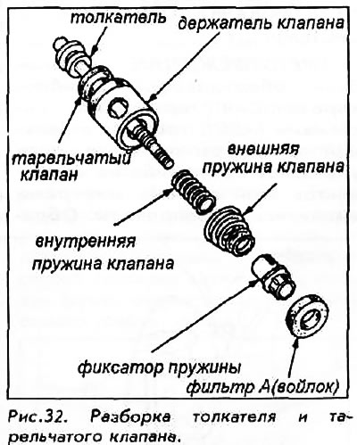
17. Remove the felt filter, spring retainer, valve springs, retainer and poppet valve from the tappet.
To install:
18. Install the poppet valve onto the valve holder.
19. Install the valve retainer, valve springs and spring retainer onto the tappet.
20. Install the felt filter and clamp.
21. Lubricate the inner and outer surfaces of the valve holder tube with silicone grease. Press the pusher assembly into the tube. Secure with a retaining ring.
22. Place the sponge filter on the end of the pushrod. Screw the adjuster and star lock nut onto the pushrod, but do not tighten them.
23. Apply silicone grease to the piston seal. Install the seal in its place on the housing. Make sure that the edges of the seal do not protrude.
24. Install the piston seal and bushing into the rear housing. Use the correct size tool to gently push the retainer 6mm below the edge of the rear housing. If the retainer is moved more than 6mm, the piston seal will be damaged.
25. Install both through bolts using the O-rings and snap rings.
26. Install the diaphragm on the amplifier platform.
27. Attach the amplifier platform to the rear casing. Make sure the keys and slots are aligned correctly.
28. Install the covers on the through bolts.
29. Lubricate the rear housing walls and the outer surface of the valve retainer assembly with silicone grease. Install the valve retainer assembly into the rear housing.
30. Lubricate the valve body walls with silicone grease. Install the reaction plate, disc and outer rod.
31. Position the mounting platform and tighten the four flange nuts to 5.5 Nm.
32. Install the booster spring. Compress the spring and install the spring retainer; install the retaining rings onto the through bolts.
33. Install washers and seals.
34. Assemble the front and rear shrouds, aligning them with the marks made earlier. Press down on the front shroud and install the retaining rings on the through bolts.
35. Adjust the tappet clearance. See separate procedure in this Chapter.
1990-91 Accord, 1991 Prelude
The manufacturer does not recommend disassembling the brake booster. If there is an internal fault, the unit must be replaced.