
Note:
- Clean disassembled parts thoroughly with solvent and dry with compressed air. Do not wash rubber parts in solvent.
- Thoroughly pack both pivots and both pivot boots with the grease supplied with the new drive shaft.
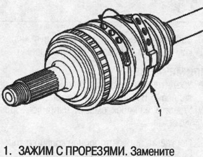
- The outer joint boot of the drive shaft is made of thermoplastic polyester elastoplastic (TPE). Fasten the outer joint boot assembly with a slotted clamp.
Amount of grease:
- Inner hinge: 130-140 g
- Outer hinge: 105-115 g
Spline (A) of the inner joint: 0.5-1.0 g (figure on the right)
From the inner hinge side
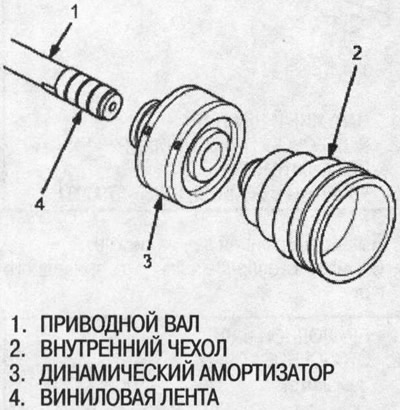
1. To avoid damaging the inner boot and dynamic shock absorber, wrap the drive shaft splines with vinyl tape.
2. Install the dynamic shock absorber and inner boot on the drive shaft, then remove the vinyl tape. Do not damage the inner boot and dynamic shock absorber.
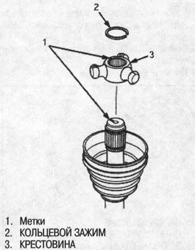
3. Install the crosspiece onto the drive shaft, aligning the marks on the crosspiece and the end of the drive shaft.
4. Place the ring clamp into the groove of the drive shaft. Rotate the ring clamp to fully seat it in the groove.
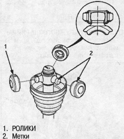
5. Place the rollers on the crosspiece with the shoulders facing outward, taking into account the following:
- Install the rollers in their original position on the crosspiece, aligning the marks.
- To prevent the rollers from falling off, hold the drive shaft vertically.
6. Pack the inner joint with the joint grease supplied with the new drive shaft.
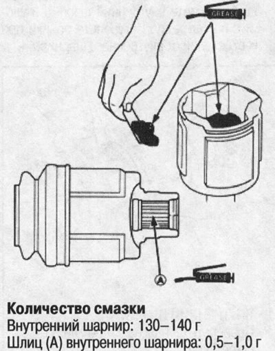
7. Place the inner joint on the drive shaft as shown in the figure, taking into account the following:
- Install the inner joint onto the drive shaft, aligning the marks on the inner joint and rollers.
- To prevent the inner joint from falling off, hold the drive shaft vertically.
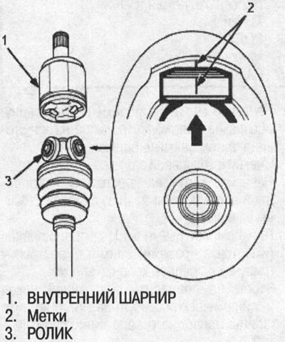
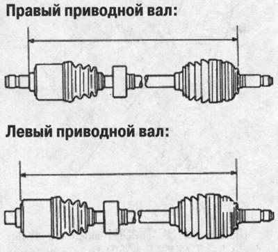
8. Adjust the length of the drive shafts as shown below, then install the boots halfway between the fully compressed and fully retracted positions. Make sure the ends of the boots fit into the grooves of the drive shaft and hinge.
Standard:
- Left drive shaft: 487-492 mm
- Right drive shaft: 506-511 mm
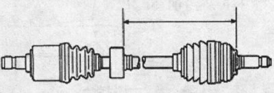
9. Install the dynamic shock absorber as shown below.
Standard:
- Left drive shaft: 251-255 mm
- Right drive shaft: 242-246 mm
10. Place the ends of the boot over the drive shaft and inner joint, then place the clips on the boots so that the end of the clip faces the front of the vehicle.
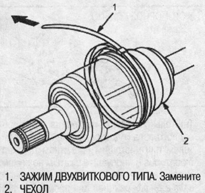
11. Remove any slack in the clamp by hand.
12. Place a mark 10-14mm from the clamp.
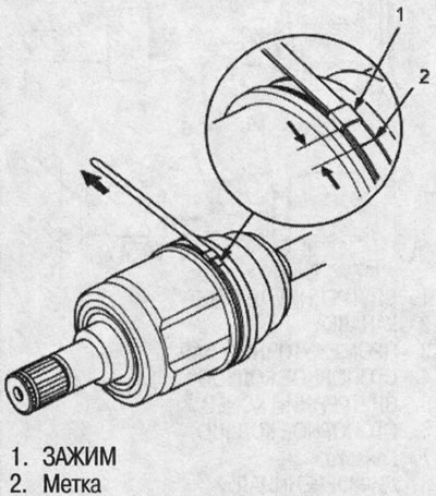
13. Pass the free end of the clamp band through the nose of the special boot clamp tightening tool KD-3191 (commercially available) or equivalent and into the slot on the rotating mandrel.
14. Place the wrench on the rotating mandrel of the special tool and tighten the clamp until the mark on the tape reaches the edge of the clamp.
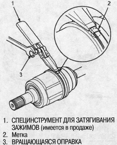
15. Raise the special tool and bend the free end of the clamp band at a 90° angle to the clamp. Mark the clamp with a center punch, then wrap the end onto the clamp.
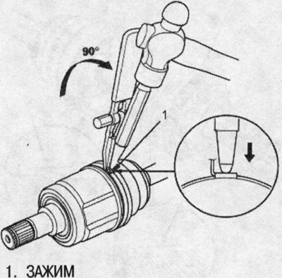
16. Release the special tool mandrel and trim off the excess tape, leaving a 5-10 mm tip protruding from the clamp.
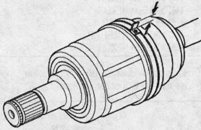
17. Bend the end of the tape by tapping it with a hammer.
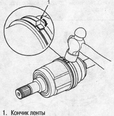
Note:
- Make sure the tape and clamp do not touch anything and the tape does not move.
- Remove excess grease from adjacent areas.
18. Install a new retaining ring.
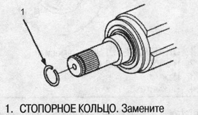
From the outer hinge side
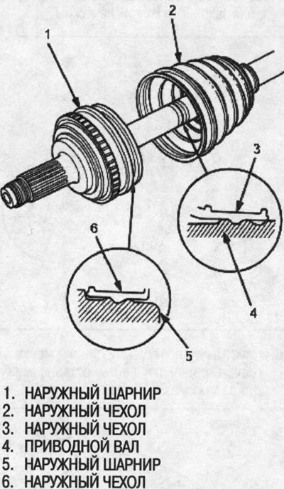
1. To avoid damaging the outer boot, wrap the drive shaft splines with vinyl tape.
2. Put on the outer cover. Do not damage the outer cover.
3. Remove the vinyl tape.
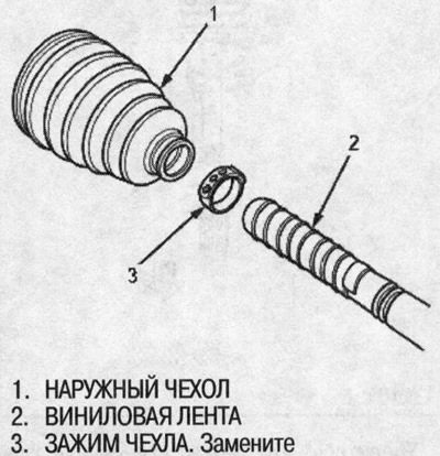
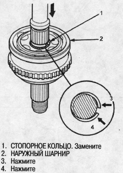
4. Place a new snap ring into the groove of the drive shaft.
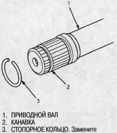
5. Insert the drive shaft into the outer joint until the retaining ring fits into the joint.
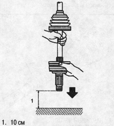
6. To fully seat the outer joint, grasp the drive shaft and joint and tap them on a hard surface from a height of about 10 cm. Do not use a hammer, otherwise you may damage the drive shaft.
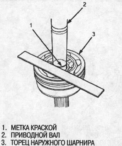
7. Make sure the paint mark is aligned with the end of the outer hinge.
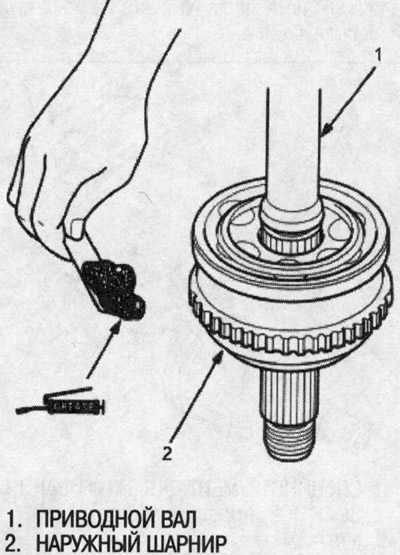
8. Pack the outer joint with the joint grease supplied with the new drive shaft.
Amount of grease: Outer joint: 105-110 g.
9. Place the ends of the boot over the drive shaft and outer joint.
10. Install the new slotted clip by threading the tabs through the slots in the tape.
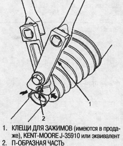
11. Crimp the U-shaped part of the clamp tape with clamp pliers (commercially available).
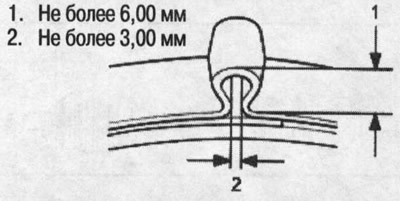
12. Check the gap in the U-shaped part of the tape. If the gap is large, tighten the U-shaped part more.
(Full version on the source website: «Hondabook.ru»)