
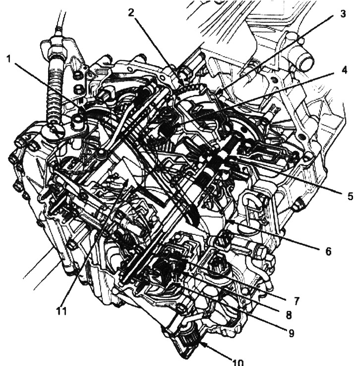
1. steel belt; 2. ring gear; 3. flywheel; 4. starting clutch; 5. drive shaft; 6. driving pulley; 7. forward clutch; 8. reverse brake; 9. set of planetary gears; 10. ATF filter; 11. driven pulley
Continuously variable transmission (CVT/Honda Multi Matic) is an automatic transmission equipped with driving and driven pulleys and a steel belt. The CVT/Honda Multi Matic transmission provides stepless shifting for forward and one for reverse. The box assembly is located in line with the engine.
Transmission
On the outside of the flywheel there is a ring gear that engages with the starter drive gear when the engine is started. There are four parallel shafts in the box: the driving shaft, the driving pulley shaft, the driven pulley shaft and the output shaft. The drive shaft is aligned with the crankshaft of the engine. On the shafts of the driving and driven pulleys, pulleys with a movable and fixed surface are fixed. Both pulleys are connected with a steel belt.
The drive shaft has a sun gear. On the shaft of the drive pulley sits the forward clutch, on the drum of which the carrier assembly is installed. The carrier consists of pinion gears that mesh with the sun gear and the ring gear. The reverse brake disc is mounted on the ring gear hub.
On the shaft of the driven pulley sits the starting clutch and the drive gear of the secondary shaft, made integral with the parking gear. The output shaft is located between the input shaft drive gear and the final drive driven gear. On the output shaft sits the driven gear of the output shaft, which serves to change the direction of rotation, since the shafts of the drive and driven pulleys rotate in the same direction. When certain combinations of planetary gears in the gearbox are engaged by the clutches and the reverse brake, power is transferred from the drive pulley shaft to the driven pulley shaft and provides movement in the L, D, R ranges.
Electronic control
The electronic control system consists of a power train control module (RSM), sensors, three linear control solenoids and one blocking solenoid. Electronic shift control provides convenience in all driving modes. The Grade Logic Control System is also available to control shifting in the D range when driving uphill or downhill. The PCM is located under the dashboard on the passenger side behind the wheel arch panel.
Hydraulic control
Bottom control valve box assembly consists of main valve body, low pressure control valve body (PL), shift valve housings, starter clutch control valve housings, and secondary valve housings. They are located at the bottom of the gearbox housing.
The main valve body includes a high pressure control valve (PH), lubrication valve and Pitot control valve.
High pressure control valve located in the secondary valve body (PH), clutch pressure reducing valve, start clutch valve accumulator and shift lock valve. In the low pressure control valve body (PL) there is a low pressure control valve (PL) and control valve PH-PL (high pressure - low pressure), which is combined with the PH-PL linear control solenoid. On the low pressure control valve body (PL) the electrovalve of blocking of a gear change is bolted.
The shift valve body houses a shift valve and shift control valve, which is combined with a linear shift control solenoid. The start clutch control valve housing is located in the start clutch control valve housing, which is combined with the start clutch linear control solenoid. The linear control solenoids and the shift lock solenoid are controlled by the PCM. A manual control valve body is bolted to the intermediate crankcase, in which the manual control valve and the reverse gear block valve are installed.
The ATF pump assembly is located on the gearbox housing and is connected to the drive shaft via sprockets and a chain. The fluid is supplied to the pulleys and the clutch through the corresponding pipes, and to the reverse brake - from the internal hydraulic circuit.
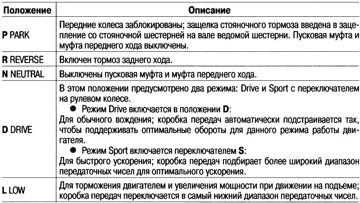
Selector lever positions
The selector lever has five positions: P PARK, R REVERSE, N NEUTRAL, D DRIVE and L LOW.
Thanks to the use of a sliding type engine start interlock switch, starting is only possible from position P and N.
Shift control mechanism
The activation of one or another linear control solenoid at the command of the PCM module is based on signals from various sensors located throughout the vehicle. When the shift linear control solenoid is activated, the pressure in the shift control valve changes, causing the shift valve to move. This creates pressure on the driving and driven pulleys, which changes their ratio. When the start clutch linear control solenoid is turned on, the start clutch control valve moves, which opens the channel, pressurizes the start clutch and engages it.
Automatic transmission range indicator
The automatic transmission range indicator on the instrument panel shows the selected range and eliminates the need to look at the console.