
Operating principle
To control gear shifting while driving uphill or downhill, the PCM compares the current driving conditions with data stored in memory, based on signals received from the vehicle speed sensor, throttle position sensor, manifold absolute pressure sensor, engine coolant temperature sensor, brake light switch signal and selector lever position signal.
Controlled lift
When the PCM determines that the vehicle is going uphill in position D, the system selects the most appropriate shift schedule (pulley ratio) according to the slope of the hill, thereby providing a smooth ride and additional power when needed. There are three uphill driving modes with different switching schedules depending on the slope of the slope stored in the PCM.
Controlled descent
When the PCM determines that the vehicle is going downhill in position D, the system selects the most appropriate shift schedule (pulley ratio) in accordance with the steepness of the descent, thereby ensuring, in combination with engine braking, a smooth ride on the descent. There are three downhill driving modes with different switching schedules depending on the steepness of the descent recorded in the PCM.
Hydraulic control
Hydraulic control is provided by the ATF pump, valves and solenoids. The drive of the pump ATF is carried out from a leading shaft. The ATF pump and drive shaft are connected by a drive chain and ATF pump sprockets. The shift lock solenoid valve and the linear control solenoids located in the valve box are controlled by the PCM. Fluid from the ATF pump flows through the PH control valve and maintains the set pressure on the drive pulley, driven pulley and manual control valve.
Lower valve box assembly consists of main valve body, low pressure control valve body (PL), shift valve housings, starter clutch control valve housings, and secondary valve housings.
Main valve body
The main valve body includes a high pressure control valve (PH), lubrication valve and Pitot control valve.
High pressure control valve (PH)
The PH control valve delivers the control pressure PH (RNS) according to control pressure PH-PL (HLC) and applies the PH pressure to the PH control valve, which also regulates the PH pressure. When downshifting, it increases the PH pressure, which increases the high PH pressure. At the same time, by relieving the reverse lock pressure (RI) on the blocking solenoid valve, the switching time is reduced.
Lubrication valve
A lubrication valve regulates and maintains lubrication pressure on each shaft. When the pressure is too high, the spring is compressed. In this case, the lubrication valve moves and opens the liquid discharge channel.
Pitot control valve
Pitot control valve regulates the pressure in the starting clutch (SC) according to engine speed in the event of failure of the electronic control system.
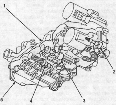
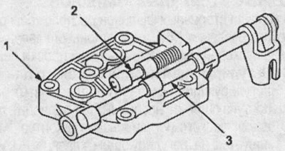
1. lower valve box assembly; 2. Pitot control valve; 3. lubrication valve; 4. PH control valve; 5. main valve body
Secondary valve body
High pressure control valve located in the secondary valve body (PH), clutch pressure reducing valve, start clutch valve accumulator and shift lock valve.
High pressure control valve (PH)
The PH control valve maintains the hydraulic pressure from the ATF pump and supplies the PH pressure to the hydraulic control circuit and the lubrication circuit. The PH pressure is adjusted at the PH control valve by the control pressure PH (RNS) from the PH control valve.
Clutch pressure reducing valve
The pressure reducing valve of the coupling is supplied with pressure PH from the control valve PH. It controls the reduction of pressure on the clutch (CR). Clutch pressure reducing valve supplies clutch pressure (CR) to the manual control valve and the start clutch control valve, and applies signal pressure to the PH-PL control valve, shift control valve and lockout solenoid valve.
Clutch valve accumulator
The start clutch valve accumulator stabilizes the hydraulic pressure supplied to the clutch.
Shift lock valve
The shift lock valve switches the control of the fluid supply to the starting clutch from electronic to hydraulic in the event of a failure of the electronic control system.
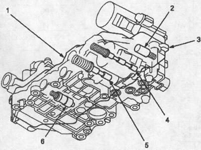
1. lower valve box assembly; 2. start clutch valve accumulator; 3. body of secondary valves; 4. shift lock valve; 5. clutch pressure reducing valve; 6. PH control valve
Low pressure control valve body (PL)
In the low pressure control valve body (PL) there is a low pressure control valve (PL) and control valve PH-PL (high pressure - low pressure), which is combined with the PH-PL linear control solenoid. On the low pressure control valve body (PL) bolted to the shift lock valve.
Low pressure control valve (PL)
Control valve PL delivers low pressure (PL) to the pulley to eliminate slippage of the steel belt.
The low pressure PL is controlled by the pilot pressure PH-PL (HLC).
Diverter valve PH-PL
The PH-PL control valve controls the PL control valve according to the engine torque. Diverter valve PH-PL delivers pilot pressure PH-PL (HLC) to the PH control valve to control the PH pressure higher than the PH-PL pressure. The control valve PH-PL is controlled by the linear control solenoid PH-PL. The latter is controlled by the TCM module.
Lockout solenoid
The lockout solenoid controls the reverse lock valve by turning on and off. In addition, the blocking solenoid regulates the control pressure PH (RNS) by supplying reverse blocking pressure (RI) to the PH control valve. The lock solenoid is controlled by the PCM.
Starting clutch control valve housing
The distribution valve of the starting clutch is located in the housing of the starting clutch control valves. Both are combined with a linear control solenoid.
Starting clutch control valve
The start clutch control valve controls the engagement of the start clutch according to the throttle opening angle. The start clutch control valve is controlled by the start clutch linear control solenoid. The latter is controlled by the PCM module.
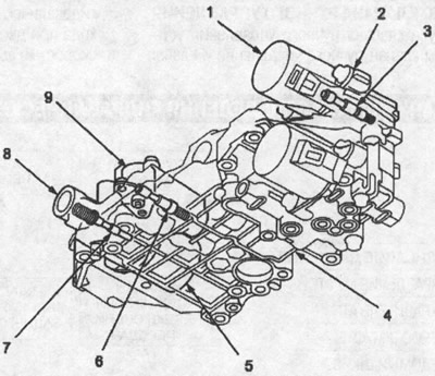
1. solenoid for linear control of the starting clutch; 2. body of distribution valves of the starting clutch; 3. distribution valve of the starting clutch; 4. bottom valve box assembly; 5. ph-pl linear control solenoid; 6. control valve PL; 7. distribution valve PH-PL; 8. control valve body PL; 9. blocking solenoid
Shift valve body
A valve and a shift control valve are installed in the housing. Both are combined with a linear shift control solenoid.
Shift valve
Shift valve controlled by pressure (SV) from the shift control valve. The shift valve distributes PH pressure and PL pressure to the driving and driven pulleys and performs gear shifting.
Shift Control Valve
The control valve controls the shift valve in accordance with the degree of throttle opening and vehicle speed. The shift control valve is controlled by the linear shift control solenoid. The latter is controlled by the TCM module. In the event of a failure of the electronic control system, the shift control valve causes the shift lock valve to open a channel that supplies pressure from the pitot regulator to the starting clutch.
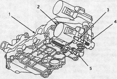
1. lower valve box assembly; 2. Linear shift control solenoid; 3. shift control valve; 4. shift valve body; 5.shift valve
Manual valve body
The manual valve body houses the manual valve and the reverse stop valve. The manual valve body is bolted to the intermediate housing.
Manual control valve
The manual valve mechanically opens/closes the fluid passage according to the position of the selector lever.
Reverse lock valve
Reverse lock valve controlled by reverse lock pressure (RI). It cuts off the hydraulic circuit to the reverse brake when the vehicle is moving forward at speeds above 10 km/h.
1. manual valve body; 2. reverse block valve; 3. manual control valve