
N-position
- Starting clutch: off
- Forward clutch: off
- Reverse brake: off
Hydraulic pressure is not supplied to the starting clutch, forward clutch and reverse brake. Power is not transmitted to the output shaft drive gear.
P position
- Starting clutch: off
- Forward clutch: off
- Reverse brake: off
Hydraulic pressure is not supplied to the starting clutch, forward clutch and reverse brake. Power is not transmitted to the output shaft drive gear. The output shaft drive gear is locked by the parking brake latch locking the parking gear.
Note: The illustration shows a 4WD automatic transmission; the power flow on the 2WD gearbox is the same as the 4WD automatic transmission, except for the components related to the transfer case.
D and L positions (forward gear range)
- Starting clutch: included
- Forward Clutch: Included
- Reverse brake: off
1. Hydraulic pressure is applied to the forward clutch and starting clutch, and the sun gear drives the forward clutch.
2. The forward clutch drives the drive pulley shaft, which drives the driven pulley shaft, which is connected by a steel belt.
3. The driven pulley shaft, through the starting clutch, drives the output shaft drive gear.
4. Power is transferred to the output shaft driven gear, which drives the final drive driven gear.
Note:
- The working hydraulic pressure on the movable surface of each shaft depends on the degree of opening of the throttle valve.
- The illustration shows a 4WD automatic transmission; the power flow on the 2WD gearbox is the same as the 4WD automatic transmission, except for the components related to the transfer case.
R-position
- Starting clutch: included
- Forward Clutch: Included
- Reverse brake: included
1. Hydraulic pressure is supplied to the reverse brake and starting clutch. The sun gear drives the gears and the pinions roll around the sun gear. The carrier assembly rotates in the opposite direction to the rotation of the sun gear.
2. The carrier assembly drives the drive pulley shaft through the forward clutch drum, and the drive pulley shaft drives the driven pulley shaft connected by a steel belt.
3. The driven pulley shaft, through the starting clutch, drives the output shaft drive gear.
4. Power is transferred to the output shaft driven gear, which drives the final drive driven gear.
Note: The illustration shows a 4WD automatic transmission; the power flow on the 2WD transmission is the same as the 4WD automatic transmission, except for the components related to the transfer case assembly.
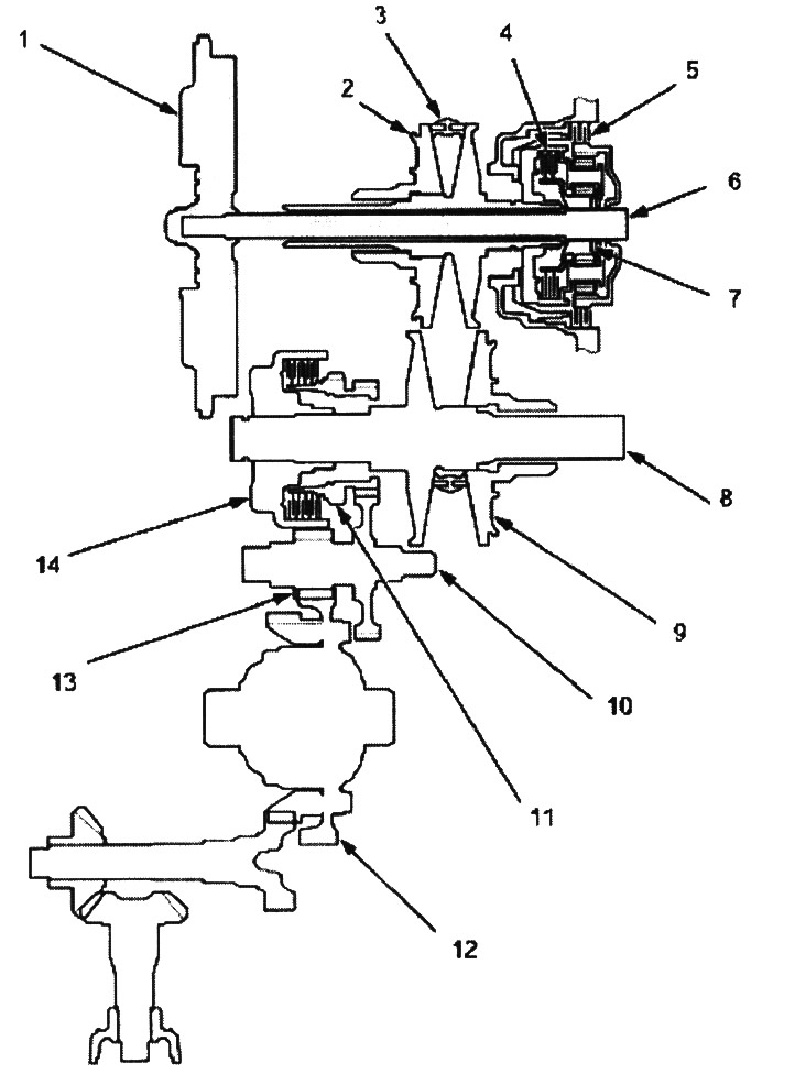
1. flywheel; 2. driving pulley; 3. steel belt; 4. forward clutch; 5. reverse brake; 6. drive shaft; 7. sun gear; 8. drive pulley shaft; 9. driven pulley; 10. output shaft drive gear; 11. parking gear; 12. final drive driven gear; 13. final drive pinion; 14. starting clutch
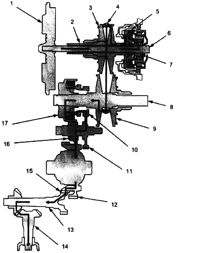
1. flywheel; 2. drive pulley shaft; 3. driving pulley; 4. steel belt; 5. forward clutch; 6. drive shaft; 7. sun gear; 8. driven pulley shaft; 9. driven pulley; 10. output shaft drive gear; 11. driven gear of the output shaft; 12. final drive driven gear; 13. transfer box shaft; 14. shaft of the driven gear of the transfer case; 15. drive gear of the transfer case shaft; 16. final drive pinion; 17. starting clutch
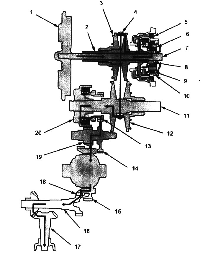
1. flywheel; 2. drive pulley shaft; 3. driving pulley; 4. steel belt; 5. reverse brake; 6. carrier assembly; 7. drive shaft; 8. sun gear; 9. satellite; 10. ring gear; 11. driven pulley shaft; 12. driven pulley; 13. output shaft drive gear; 14. driven gear of the secondary shaft; 15. final drive driven gear; 16. transfer box shaft; 17. shaft of the driven gear of the transfer case; 18. drive gear of the transfer case shaft; 19. final drive pinion; 20. starting clutch