
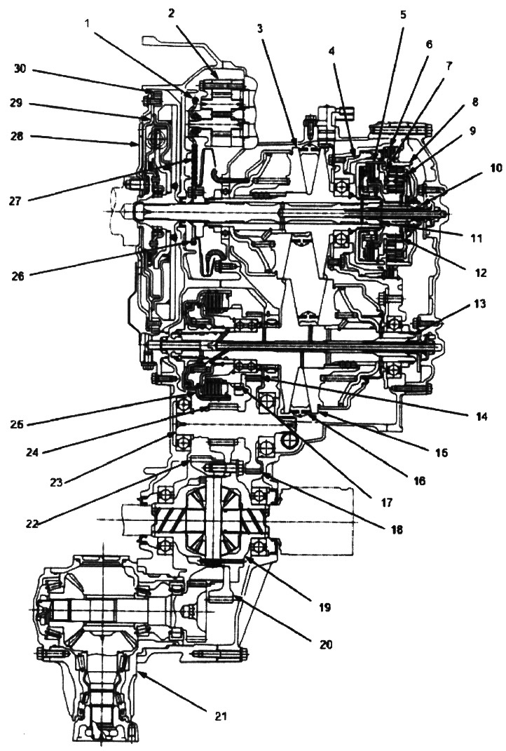
1. ATF pump drive sprocket; 2. ATF pump; 3. driving pulley; 4. reverse brake piston; 5. forward clutch; 6. reverse brake; 7. carrier; 8. ring gear; 9. satellite; 10. drive shaft; 11. drive pulley shaft; 12. sun gear; 13. driven pulley shaft; 14. output shaft drive gear; 15. driven pulley; 16. steel belt; 17. parking gear; 18. driven gear of the secondary shaft; 19. differential assembly; 20. final drive driven gear; 21. transfer case assembly (4WD model); 22. transfer case shaft drive gear (4WD model); 23. secondary shaft; 24. final drive pinion; 25. starting clutch; 26. ATF pump drive sprocket; 27. ATF pump drive circuit; 28. drive disk; 29. flywheel; 30. ring gear
Note: The illustration shows a 4WD automatic transmission (sectional view); The 2WD gearbox is missing the transfer case assembly and the transfer case shaft drive gear on the differential assembly.
Clutch/reverse brake
The variator uses hydraulic clutches and a brake to engage and disengage the automatic transmission gears. When hydraulic pressure is applied to the clutch drum and reverse brake piston chamber, the clutch piston and reverse brake piston move. In this case, the driven friction and driving steel disks are pressed against each other and blocked in this state, excluding slippage. Power is transmitted through the engaged clutch assembly to the hub-mounted gear and through the engaged ring gear to the pinion gears. Similarly, when hydraulic pressure is removed from the clutch assembly and the reverse brake piston cavity, the piston unclenches the friction and steel discs, which can rotate without hitting each other. In this case, the gear rotates independently on its shaft and no power is transmitted.
Starting clutch
The starting clutch, located at the end of the driven pulley shaft, engages and disengages the input shaft drive gear. Hydraulic pressure is supplied to the starter clutch through the ATF supply pipes in the driven pulley shaft.
Forward clutch
The forward clutch, located at the end of the drive pulley shaft, engages and disengages the sun gear. The hydraulic pressure to the forward clutch is supplied through the ATF supply pipes in the drive pulley shaft.
Reverse brake
The reverse brake, located inside the intermediate case around the ring gear, locks the ring gear in the R position. The reverse brake discs are mounted on the ring gear and the reverse brake pressure plates are mounted on the intermediate case. Hydraulic pressure to the reverse brake is supplied through a circuit connected to the internal hydraulic circuit.
Planetary gear
The planetary gear consists of the sun gear, the carrier assembly and the ring gear. The sun gear is connected to the splined drive shaft. The satellites are mounted on the carrier, which is located in the forward clutch drum. The sun gear brings power from the engine through the drive shaft to the planetary gear, and the planet carrier supplies power to the engine. The ring gear is only used to change the direction of rotation of the pulley shafts.
In positions D and L (forward gear range) the pinion gears do not rotate or roll around the sun gear, so the planet carrier rotates. In position R (reverse range) the reverse brake blocks the annulus and the sun gear causes the pinions to rotate. The planet gears rotate and roll in the opposite direction of the sun gear rotation, and the planet carrier rotates with the planet gears.
Pulleys
Each pulley consists of a movable and a fixed surface and the gear ratio changes depending on the engine speed. The driving and driven pulleys are connected by a steel belt.
To obtain a low gear ratio, high hydraulic pressure is applied to the movable surface of the driven pulley, which reduces the average diameter of the drive pulley, and low hydraulic pressure is applied to the movable surface of the drive pulley to eliminate slippage of the steel belt. To obtain a high gear ratio, high hydraulic pressure is applied to the movable surface of the driven pulley to eliminate slippage of the steel belt.
Transfer mechanism (4WD)
The transfer mechanism consists of the transfer case shaft drive gear, the transfer case shaft, the transfer case drive gear, the transfer case shaft driven gear and the connecting flange. The transfer case assembly is located at the rear of the transmission, next to the differential. The transfer case shaft drive gear on the final drive driven gear drives the transfer case shaft driven gear. Power to the rear differential is transmitted through the transfer case shaft and driveshaft.