
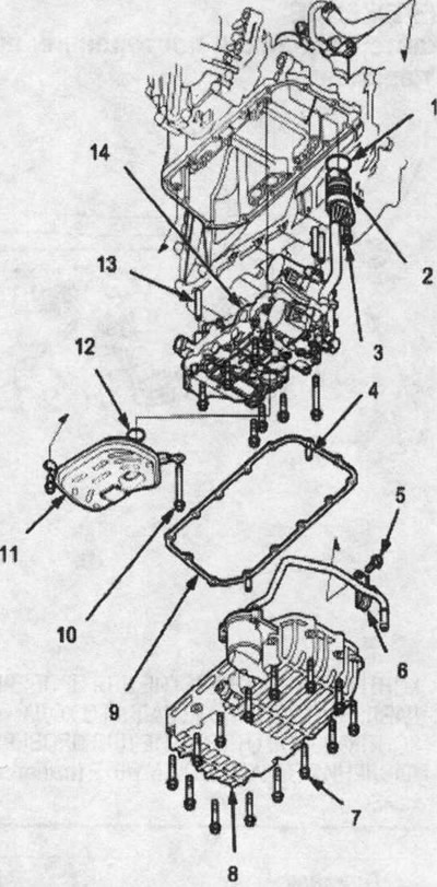
1. O-ring. Replace
2. SOLENOID HARNESS CONNECTOR
3. 6x1.0 mm
4. REFERENCE PIN
5. 8x1.25 mm, 26 Nm (2.7 kgf/m)
6. ATF FEED PIPE BRACKET
7.6x1.0mm
8. ATF PAN
9. GASKET UNDER THE PAN FOR ATF LIQUID. Replace
10. 6x1.0 mm
11. ATF STRAINER
12. O-ring. Replace
13. REFERENCE PIN
14. LOWER VALVE BOX ASSEMBLY
Warning!
- Make sure the lifts, jacks and safety stands are installed correctly.
- Apply the parking brake and block the rear wheels so that the vehicle does not roll off the bed and fall on you while you are working under it.
Warning! When removing and installing the lower valve box, do not allow dust and other foreign objects to enter the gearbox.
1. Raise the front of the vehicle and secure it securely.
2. Set the parking brake and chock both rear wheels.
3. Remove the drain plug and drain the transmission fluid. Screw the plug into the drain hole with a new sealing washer (see above).
4. Disconnect the solenoid harness connector.
5. Disconnect the ATF cooler supply hose from the cooler tube. To prevent ATF from escaping, turn the end of the hose up, then plug the hose and tube.
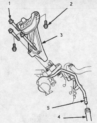
1. 10x1.25 mm, 54 Nm (5.5 kgf/m)
2. 10x1.25 mm, 44 Nm (4.5 kgf/m)
3. FRONT RIGHT SUPPORT/BRACKET
4. ATF SUPPLY HOSE
5. ATF COOLER SUPPLY PIPE
6. Remove the front right support/bracket.
7. Turn off a bolt of an arm of a giving pipe of cooler ATF.
8. Remove the ATF sump (14 bolts).
9. Remove the ATF pre-filter, then remove the bolt securing the solenoid harness connector.
10. Remove lower manifold assembly (8 bolts) (drawing on the next page above).
Tightening torque: 6x1.0 mm bolts in this illustration 12 Nm (1.2 kgf/m)
11. Install the lower valve box assembly in the reverse order of removal.
Note:
- During installation, replace the following components:
- O-rings
- ATF pan gasket
- sealing washer
12. Calibrate the clutch control feedback signal in the PCM module memory (see above).