
Note: Left hand drive model shown; the layout on the right-hand drive model is similar.
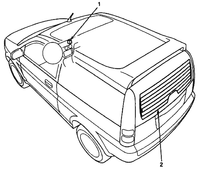
Testing the switch
1. Remove the center section of the instrument panel (see chap. "Body").
2. Disconnect the 5-pin connector from the switch.
3. Press the switch from behind the center section and pull it out.
4. Check for conductivity between the contacts in all switch positions in accordance with the table.
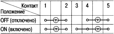
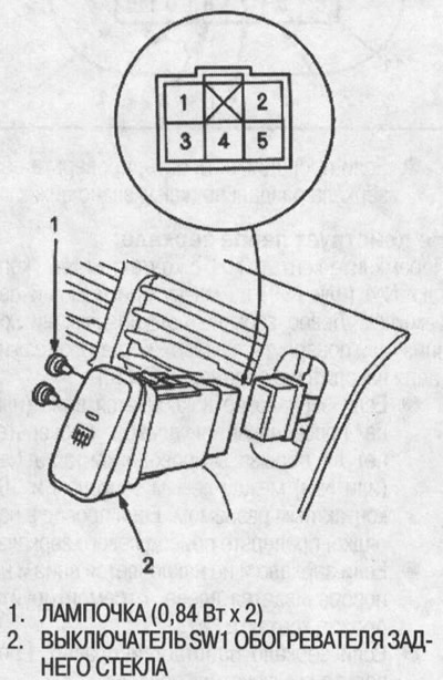
Checking functionality
Note: Do not scratch or damage the heater wires with the tester probes.
1. Check the voltage between the positive terminal and ground when the ignition key and heater switch are in the ON position. There should be battery voltage.
- If there is no voltage, check:
- Is the heater switch working properly?.
- Is there a break in the BLACK-BLUE wire?.
- Poor grounding (G401, G402, G501).
- If there is voltage, proceed to step 2.
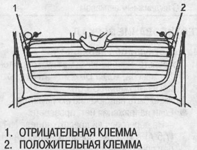
2. Check for continuity between the negative terminal and ground. If there is no continuity, check for a break in the heater ground wire.
3. Touch the positive probe of the voltmeter to the midpoint of each heater wire and the negative probe to the negative terminal. There should be about 6 V when the ignition key and heater switch are in the ON position.
- If the voltage is normal, the heater wire is OK.
- If the voltage is not normal, repair the heater wire.
- If the voltage is greater than 6 V, there is a break in the negative half of the wire.
- If the voltage is less than 6 V, there is a break in the positive half of the wire.
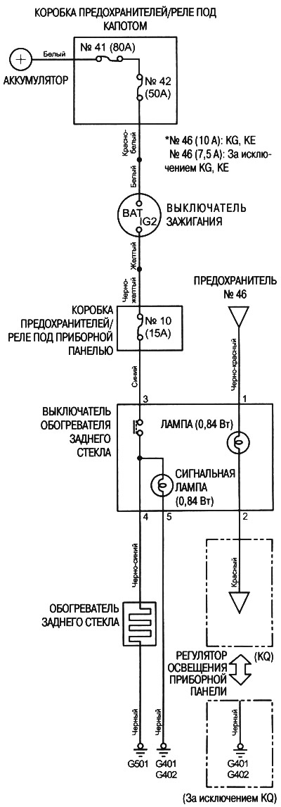
Electrical diagram
Heater Wire Repair
Note: For the repair to be effective, the length of the torn section should not exceed 2.5 cm.
1. Lightly sand the area around the torn area with fine steel mesh, then clean with alcohol.
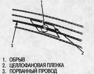
2. Carefully apply cellophane tape over the top and bottom of the torn section of the heater wire.
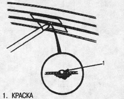
3. Using a small brush, apply a thick coat of conductive silver paint so that it extends approximately 0.3 mm on both sides of the break. Allow to dry for 25 minutes. Stir the paint thoroughly before applying.
4. Check for conductivity in the repaired wire.
5. Apply a second coat of paint in the same manner. Allow to dry for three hours before removing the film.