
Contents: Checking functionality ⇊ Testing mirrors ⇊ Testing the Power Mirror Switch ⇊ Testing the mirror drive ⇊ Testing the heater ⇊ Replacing the mirror drive ⇊
Note: Left hand drive model shown; the arrangement on the right-hand drive model is symmetrical.
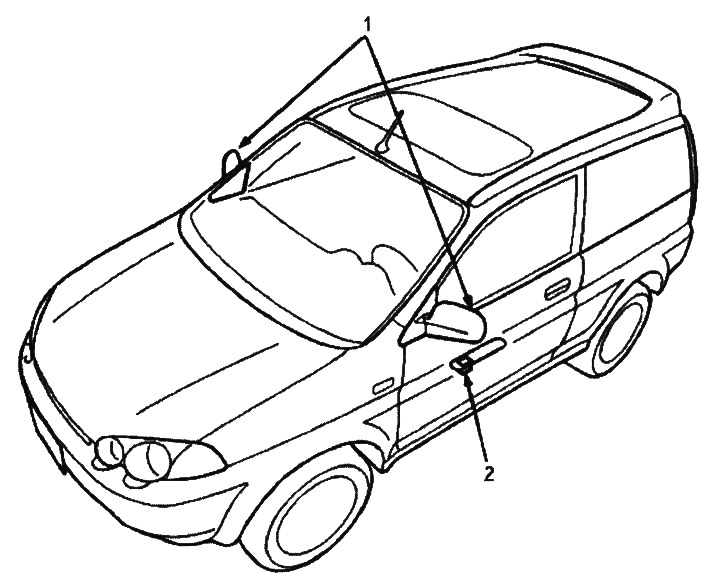
1. Electric mirror
2. Power mirror switch
Checking functionality
1. Remove the driver's side door panel.
2. Disconnect the 10-pin connector from the power mirror switch.
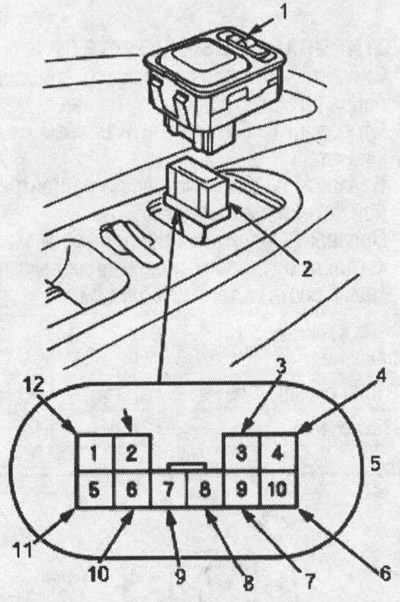
1. ELECTRIC MIRROR SWITCH
2. 10-PIN CONNECTOR
3. BLACK AND YELLOW
4. RED-YELLOW WIRE
5. Female connector on the harness side
6. BLACK-BLUE [BLACK-YELLOW] WIRE
7. BLACK-YELLOW [BLACK-BLUE] WIRE
8. LIGHT BLUE [WHITE-GREEN] WIRE
9. WHITE-GREEN [LIGHT BLUE] WIRE
10. *1 BLUE-YELLOW, *2 ORANGE-GREEN WIRE
11.YELLOW-GREEN WIRE
12. BLACK-YELLOW WIRE
13. BLACK WIRE
[]: RIGHT DRIVE
*1: With heater
*2: With retractable mirror
Testing mirrors
Both mirrors are not working:
1. Check the voltage between terminal #1 and ground when the ignition switch is in the ON (II) position. There should be battery voltage.
- If there is no voltage, check:
- Is fuse #11 (7.5A) in the under-dash fuse/relay box blown?.
- Is there a break in the BLACK-YELLOW wire?.
- If there is voltage, proceed to step 2.
2. Check for continuity between contact #2 and ground. There should be continuity.
- If there is no conductivity, check:
- Is there a break in the BLACK wire?.
- Poor grounding (G401, G402).
- If there is continuity, check both mirrors separately as described below.
The left mirror does not work:
Short contact #1 to contact #7, contact #4 (or #9) to ground using jumpers. The left mirror should tilt down (or turn left) when the ignition key is in the ON (II) position.
- If the mirror does not tilt down (or does not rotate to the left), check for a break in the wire at pin #4 (or #9) between the left mirror and the 10-pin connector. If the wire is OK, check the left mirror drive.
- If the mirror does not tilt down and does not turn to the left, repair the wire of contact #7.
- If the mirror is working properly, check the mirror switch.
The right mirror does not work:
Short contact #1 to contact #8, contact #4 (or #10) to ground using jumper wires. The right mirror should tilt down (or turn left) when the ignition switch is in the ON (II) position.
- If the mirror does not tilt down (or does not rotate to the left), check for a break in the wire at pin #4 (or #10) between the left mirror and the 10-pin connector. If the wire is OK, check the left mirror drive.
- If the mirror does not tilt down and does not turn to the left, repair the wire of contact #8.
- If the mirror is working properly, check the mirror switch.
Testing the heater:
Connect pin #3 to pin #6 with a jumper wire and check for voltage between pin #3 and ground. There should be battery voltage and both mirrors should warm up when the ignition switch is in the ON (II) position.
- If there is no voltage or none of the mirrors warm up, check:
- Is there a break in the BLACK-YELLOW and BLUE-YELLOW wires?.
- Is fuse #11 (7.5A) in the under-dash fuse/relay box blown?.
- Poor grounding (G401, G402).
- If only one mirror does not warm up, check its heater.
- If both mirrors do not heat up, check the heater switch.
The retractable mirror does not work
Shorten pin #1 (BLACK-YELLOW) of the 10-pin connector and pin #6 (YELLOW-GREEN) to ground using a jumper wire. The mirrors should extend when the ignition key is in the ON (II) position. _ Shorten pin #1 (BLACK-YELLOW) of the 10-pin connector to pin #5 (YELLOW-GREEN), pin #6 (GREEN-ORANGE) to ground using a jumper wire. The mirrors should retract when the ignition key is in the ON (II) position.
- If one of the mirrors does not retract or extend, check the retractable mirror drive.
- If the mirrors work properly, replace the switch.
Testing the Power Mirror Switch
1. Remove the driver's side door panel.
2. Disconnect the 10-pin connector from the power mirror switch.
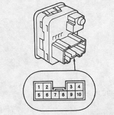
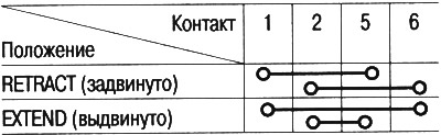
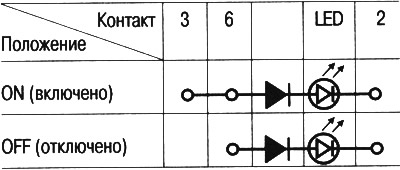
3. Check for conductivity between the contacts in all switch positions in accordance with the table.
Power Mirror Switch
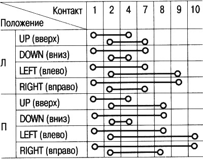
Retractable mirror switch
Heater switch
Testing the mirror drive
1. Remove the door panel.
2. Disconnect the 3-pin or 6-pin connector from the power mirror.
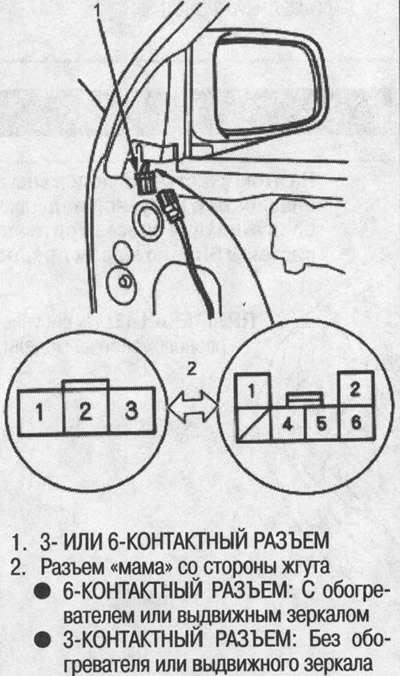
3. Check the operation of the drive by supplying power and grounding according to the table.
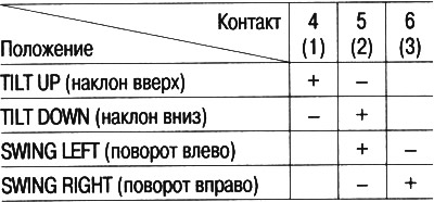
(): Without heater or retractable mirror
Testing the heater
4. Check for continuity between contacts #1 and #2 of the 6-pin connector. There should be continuity.
5. If the mirror does not work properly, replace the mirror drive.
Retractable mirror drive:
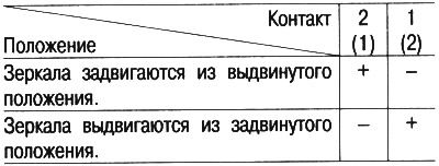
(): On the right side
Replacing the mirror drive
1. Remove the power mirror from the door (see chap. "Body") and disconnect the 6-pin or 3-pin connector.
2. Cut the wiring harness with wire cutters.
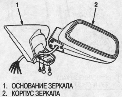
3. Remove the mirror base.
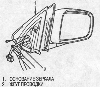
4. Unscrew the mounting bolts and separate the base from the mirror housing.
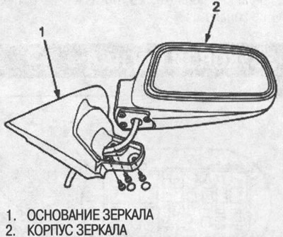
5. Insert the flat blade of a screwdriver into the two slots. The mirror is attached to the drive with double-sided adhesive tape. Gently twist the screwdriver and release the mirror. (To protect the paintwork, place a napkin between the screwdriver and the mirror housing.).
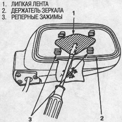
6. Unscrew the screws and remove the drive from the housing.
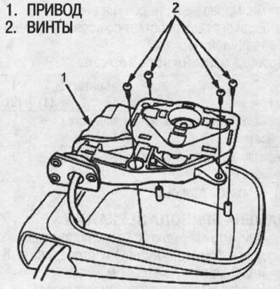
7. Installation is performed in the reverse order of removal. Replace the base and three screws with new ones.
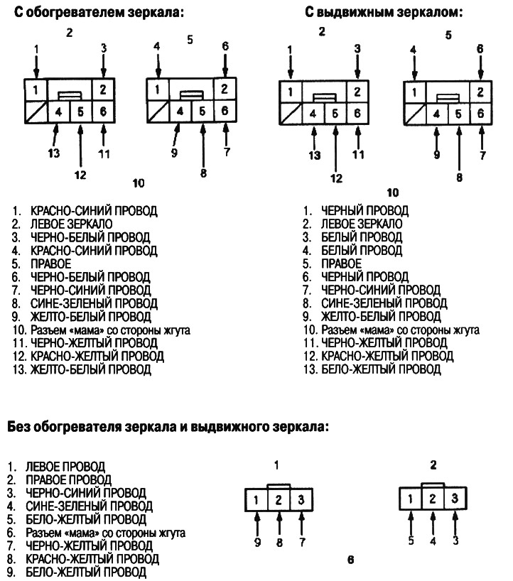
8. Insert the contacts into the connector in the original order as shown in the figure.
The original can be found on the resource HondaBook.ru