
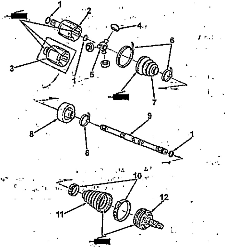
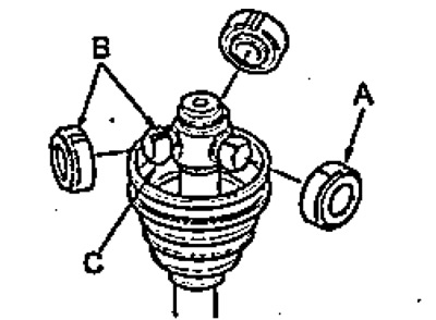
Disassembly and assembly of front drive shafts (right hand drive models).
1 - retaining ring,
2 - outer cage of the inner hinge (left shaft),
3 - outer cage of the inner hinge (right shaft),
4 - roller,
5 - internal hinge,
6 - clamp (type 1),
7 - cover of the internal hinge;
8 - dynamic damper,
9 - drive shaft,
10 - clamp (type 2),
11 - cover of the external hinge,
12 - external hinge.
Internal hinge
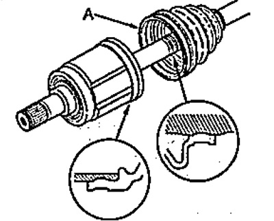
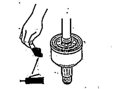
1. Wind up the protective tape (A) to the drive shaft.
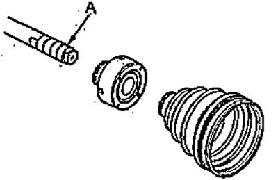
Left hand drive models.
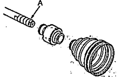
Right hand drive models.
2. Install the dynamic damper and boot on the drive shaft.
3. Remove the protective tape.
4. Align marks (A) on the drive shaft (WITH) and inner hinge (IN) and install the hinge.
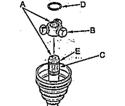
5. Install retaining ring (D) into a groove (E) drive shaft.
6. Install rollers (A) on the inner hinge (WITH) according to labels (IN).
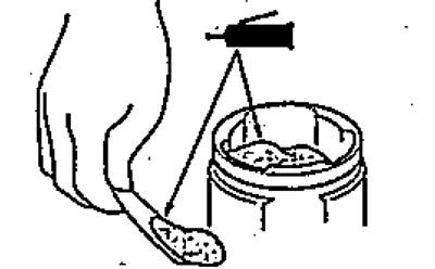
7. Fill the outer race of the inner joint with grease.
Grease quantity for drive shafts:
- right-hand drive and 2WD models - 70-80 g
- except for right-hand drive and 2WD models - 100-110 g
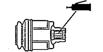
8. (Right hand drive and 4WD models)
Apply grease to the splines of the outer race of the inner joint.
- Grease - CS#7
- The amount of lubricant - 0.5 - 1.0 g
9. Install outer race (IN) inner hinge, aligning marks (WITH) on rollerskates (A) and outer cage.
10. Put on a case (A) to the outer edge.
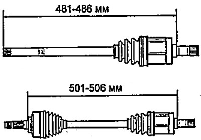
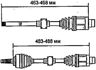
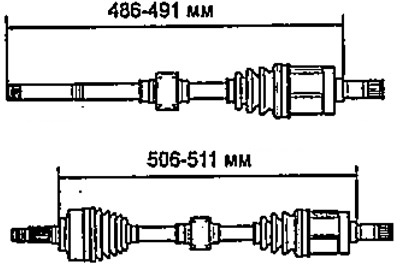
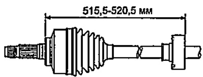
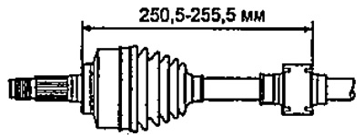
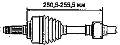
11. Adjust the position of the outer race of the inner joint so that the distances indicated in the figures correspond to the norm.
(Left hand drive models)
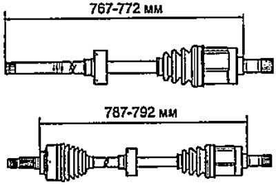
Models with manual transmission, right shaft.
Models with manual transmission, left shaft.
Models with automatic transmission, right shaft.
Models with automatic transmission, left shaft.
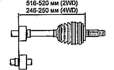
(Right hand drive models)
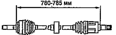
2WD models.
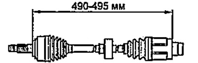
4WD models.
12. Adjust the position of the dynamic damper so that the 'distances' indicated in the figures correspond to the norm.
(Left hand drive models)
Models with manual transmission.
Models with automatic transmission, right shaft.
Models with automatic transmission, left shaft.
(Right hand drive models)
13. (Clamp type 2)
Slide the end of the clamp onto the retainer as shown.
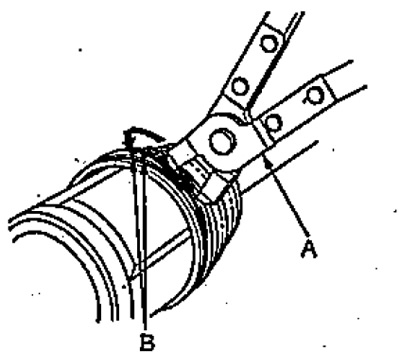
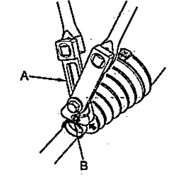
14. (Clamp type 2)
With the help of pliers (A) align the holes of the clamp and the clamps (IN).
15. (Clamp type 1)
Pass the yoke (A) through the latch (IN) two times to make two loops.
16. (Clamp type 1)
Tighten the clamp (A) and put a mark on the collar so that the distance between the mark (WITH) and fixative (IN) was 10 - 14 mm.
17. (Clamp type 1)
Install special tool (A) and by turning the adjusting bolt (IN), tighten the clamp so that the latch is installed on the mark (WITH).
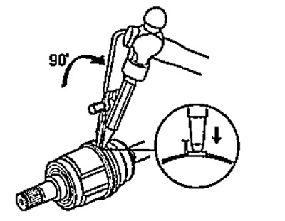
18. (Clamp type 1)
Rotate the tool 90°as shown in the illustration and screw the lock in the center.
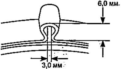
19. (Clamp type 1)
Cut the clamp so that the distance shown in the figure is 5-10 mm.
20. (Clamp type 1)
Bend the collar (A), as it shown on the picture.
External hinge
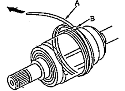
1. Wind up the protective tape (WITH) on the splines of the drive shaft (A) from the side of the outer hinge.
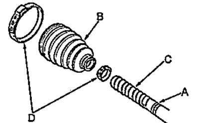
2. Install clamps (D) and case (IN) to the drive shaft.
3. Remove the protective tape.
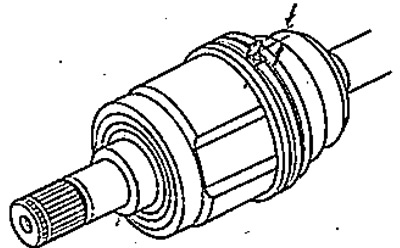
4. Install retaining ring (IN) into a groove (A) drive shaft.
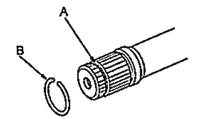
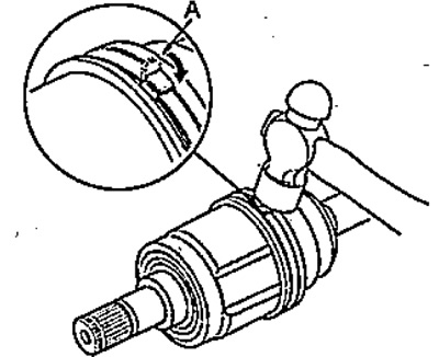
5. Press the circlip (A) in the places shown in the figure, and install the drive shaft (WITH) in the hinge (IN).
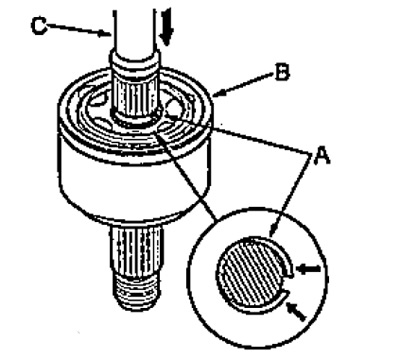
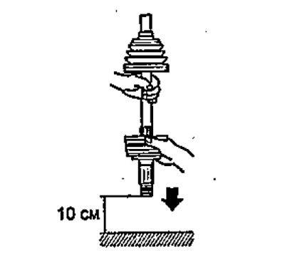
6. Finally install the drive shaft into the joint as shown in the figure.
Note: When performing the procedure, keep the alignment of the drive shaft and the pivot shaft.
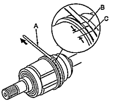
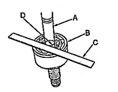
7. Using a ruler (A) make sure the label (B) is at the level of the hinge end (C).
8. Apply grease to the hinge.
- Grease - Nissekl Mitsubishi U2600-70
Amount of lubricant:
- Left hand drive models - 35 g
Right hand drive models:
- 2WD - 60-70 g
- 4WD - 95-105 g
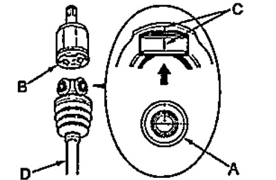
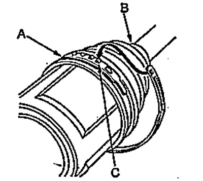
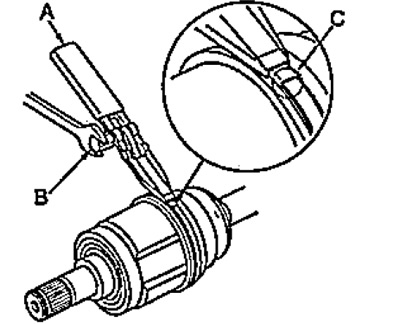
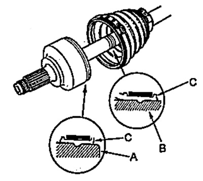
9. Install the case (C) so that it sits in the grooves of the drive shaft (B) and hinge (A), as it shown on the picture.
10. Using the special tool, tighten the clamp so that the dimensions of the loop correspond to those shown in the figure.
 |  |
11. Make sure the clamps are not loose. Remove any escaping grease.