
Contents: Checking the camber angle ⇊ Checking and adjusting the…⇊ Checking and adjusting the alignment…⇊ Checking and adjusting the front…⇊
All components of the wheel installation are connected to each other. Therefore, when adjusting one of the elements, it is necessary to check the other components and, if necessary, perform a general adjustment.
Before checking and adjusting, please ensure the following conditions are met.
- Park the car on a level surface.
- Unload the vehicle (full fuel tank, spare tire, jack and tool kit removed from the vehicle).
- Release the vehicle's parking brake.
- When releasing the parking brake, depress the brake pedal with a brake pedal compressor (commercially available) so that the vehicle does not move. To prevent the brake lights from illuminating, remove the brake light fuse.
- For details on using the devices, please refer to the relevant device instructions.
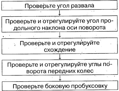
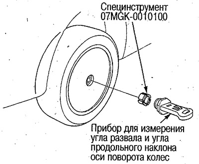
Checking the camber angle
1. Remove the center cap.
2. Install the device for measuring the camber angle and the longitudinal tilt angle of the steering axis on the end of the hub through an adapter (special tool).
3. Set the front wheels to a position corresponding to the straight-ahead movement of the vehicle.
4. Read the camber reading on the instrument by moving the instrument level bubble to the center.
Camber angle:
Front wheels:
- 0°00'±1° (2WD models).
- 0°20'±1° (4WD models).
Rear wheels: -1°00'±1°
Maximum difference between front and rear wheels: 1°
The camber angle is not adjustable. If the camber angles are different from those specified, check the suspension components and body for deformation.
Checking and adjusting the longitudinal tilt angle of the steering axis
Examination
1. Remove the wheel center caps.
2. Carefully place the front wheels on the centers of the wheel angle gauges, and place supports of the same thickness as the gauges under the rear wheels.
Attention:
- Do not run over the gauges as the gauges may fly out or break.
- Check the horizontal position of the vehicle after installing it on the gauges.
3. Remove the locking pins from the gauges and set the front wheels to a position corresponding to the straight-ahead movement of the vehicle.
4. Install the device for measuring the camber angle and the longitudinal tilt angle of the steering axis on the end of the hub through an adapter (special tool).
5. Turn the wheel on which the camber and caster angle measuring device is installed outward by 20° and bring the level bubble to the center.
6. Turn the device regulator until the device level bubble reaches the "0" mark.
7. Return the front wheels to the straight-ahead position and then turn 20° inward. Bring the level bubble to the center and read the reading on the level of the camber angle and steering axis pitch gauge.
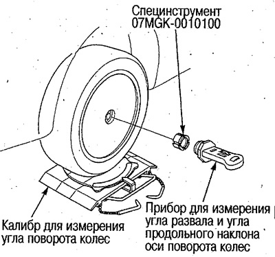
Angle of longitudinal inclination of the axis of rotation:
Standard values:
- 2WD models: 2°55'±1°
- 4WD models: 2°35'±1°
8. If the measured values are not within the standard, record the values and make adjustments.
If the measured caster angle values are outside the standard value of ±1°35', check the trailing arms or subframe for deformation.
Adjustment
The longitudinal tilt angle of the pivot axis is adjusted by selecting the number of adjusting washers. To adjust, it is necessary to disconnect the longitudinal rod.
1. Using a jack, raise the front of the vehicle and install supports.
2. Disconnect the longitudinal rods (see below).
3. Select the number of adjusting washers so that the measured value of the longitudinal tilt angle of the steering axis corresponds to the standard.
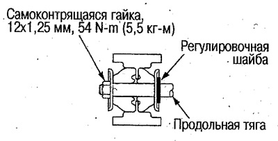
One or two adjusting washers are installed.
With one washer (thickness 3.2 mm) the angle changes to 35'.
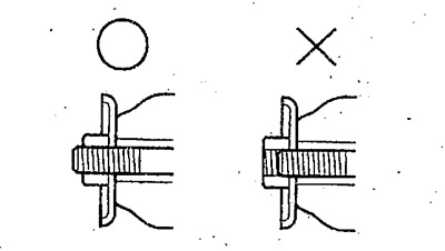
If the self-locking nut (12 mm) does not fully screw onto the longitudinal rod thread, check the longitudinal rod and subframe for deformation.
Checking and adjusting the alignment check
Examination
1. To stabilize the suspension, move the vehicle forward and backward approximately 1m.
2. Set the height of the toe-in gauge rods to the height of the vehicle axle and position it behind the wheels.
3. Place marks on the centres of the treads at a height equal to the height of the vehicle axle and use a toe gauge to measure the distance (a) between the centres of the left and right treads.
4. Slowly move the vehicle straight forward so that the marks made in step 3 are rotated 180°.
5. Measure the distance (b) between the centers of the left and right treads.
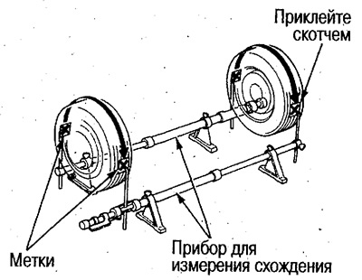 |
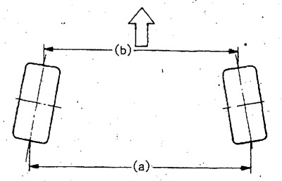 |
6. Calculate the convergence value as the difference between distances (a) and (b).
Standard alignment:
- Front wheels: 0±2 mm
- Rear wheels: 2+2 mm
Apply marks at the vehicle axle height.
When measuring the front wheel alignment, set them to positions that correspond to the vehicle moving in a straight line.
Adjustment
If front wheel alignment needs to be adjusted, proceed as follows:
Loosen the tie rod end locknuts and adjust the toe-in by rotating both steering rack ends.
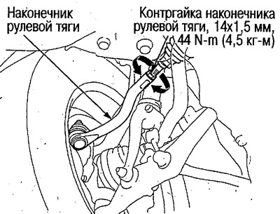
After adjustment, tighten the lock nuts.
After finishing the work, check whether the rack tip covers are twisted or have come off. Correct if necessary.
If rear wheel alignment needs to be adjusted, proceed as follows:
Loosen the lock nut on the back of the control arm.
Adjust the toe-in with the adjusting cams by turning the adjusting bolt.
After adjustment, replace the self-locking nut with a new one and tighten it to the required force, fixing the position of the adjusting bolt.
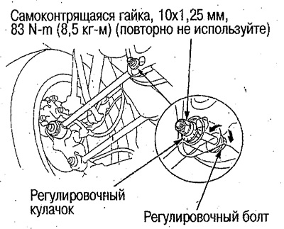
Checking and adjusting the front wheel steering angle
1. Carefully place the front wheels on the centers of the turntables of the wheel angle measuring gauges, and place supports of the same thickness as the gauges under the rear wheels.
Check the horizontal position of the vehicle after installing it on the gauges.
2. Remove the locking pins from the gauges, turn the steering wheel left and right until it stops and check the turning angles of the front wheels.
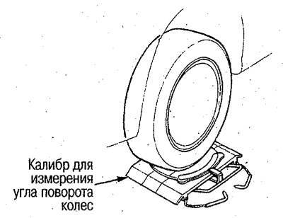
Standard front wheel steering angles:
By inner turning radius:
- 2WD models: 39°00'±2°
- 4WD models: 38°00'±2°
Outside turning radius: 31°00'
3. If the inside radius turning angles when turning left and right are different or not within the standard, adjust by turning the rack tips, and then check and adjust the toe-in (see above).
After finishing the work, check whether the rack tip covers are twisted or have come off. Correct if necessary.
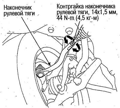
Checking for lateral wheel slip
1. Check the lateral wheel slip using a slip tester.
2. Determine the amount of wheel slip when the vehicle moves forward by 1 m.
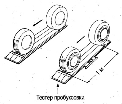
- Standard lateral wheel slip: 0±3 mm
3. If the lateral wheel slip differs from the specified value, check the front wheel alignment angles.
[The text was taken from the website «HONDABOOK»]