
HondaBook.ru
Auto companies Volkswagen Auto companies Ford Auto companies Lada Auto companies Skoda Auto companies BMW Auto companies Mazda Auto companies Peugeot
English Русский
Български
Беларускі
Український
Српски
Hrvatski
Română
Polski
Slovenský
Magyar
Bookmark Contacts Sitemap   


Accord Civic Fit / Jazz CR-V HR-V Others Articles
HR-V 1 (1998-2006, petrol)

Troubleshooting procedures (Honda HR-V 1)

  • Main
  • Honda HR-V
  • 1 (1998-2006, petrol)
  • Transmission
  • Automatic gearbox
  • Troubleshooting procedures
0
Contents: Procedure for resetting the PCM…⇊ Final procedure ⇊
When the PCM detects an abnormality in any of the input or output signals from the various systems, the D indicator lamp in the instrument cluster will flash. If the diagnostic connector (located under the instrument panel on the passenger side) is shorted using the special tool as shown in the illustration, the D indicator lamp will flash diagnostic trouble codes (DTCs) when the ignition switch is in the ON (II) position.

If the D indicator lamp lights up, short-circuit the diagnostic connector using a special tool.

Then turn the ignition key to the ON (II) position and observe the flashing (blinking) of the D indicator lamp.
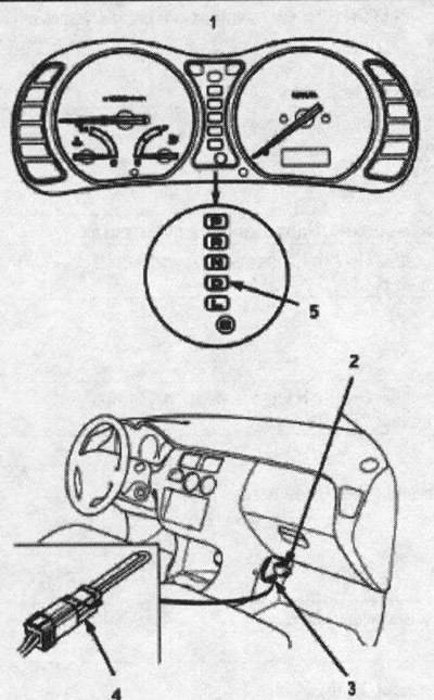
1. instrument cluster; 2. Data connector (3-pin);…

1. instrument cluster; 2. Data connector (3-pin); 3. diagnostic connector (2-pin); 4. diagnostic connector jumper, 07PAZ-0010100; 5. signal lamp


Codes 1 through 9 are indicated by separate short flashes. Codes 10 and above are indicated by a series of long and short flashes. One long flash equals 10 short flashes. To determine the code, add the long and short flashes together. Once you have determined the code, refer to the electrical equipment fault table (see below).
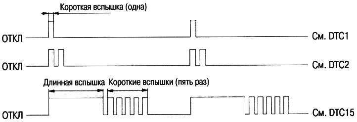


Codes 1 through 9 are indicated by separate short…


If a fault occurs in the PGM-F1 main relay, the D indicator lamp will also illuminate. After correcting the fault in the PGM-FI main relay, remove the BACK UP (7.5 A) fuse from the under-dash fuse/relay box for 10 seconds and reset the PCM, then retest.

Note: Removing the BACK UP fuse also erases the preset station frequencies, time setting, and clutch feedback signal from memory. Before removing the fuse, write down the station frequencies so that you can input them later, and refer to the appropriate procedures below to re-enter the clutch feedback signal into memory.


1. Remove the glove box (see chapter "Body").

2. Remove the PCM module.

Note: The picture shows the right-hand drive model; the arrangement on the left-hand drive model is symmetrical.
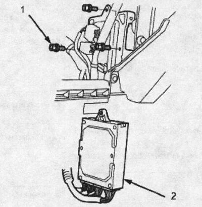

Note: The picture shows the right-hand drive…


3. Check the PCM electrical circuit according to the troubleshooting flow chart using a digital multitester equipped with cone-tip probes.
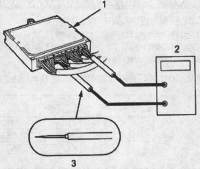


1. RCM MODULE

1. RCM MODULE
2. DIGITAL MULTI-TESTER. Available for sale or 07411 -0020000
3. TEST PROBE WITH CONICAL TIP


Procedure for resetting the PCM module


1. Turn the ignition key to the OFF position.

2. Remove the BACK UP (7.5A) fuse from the under-dash fuse/relay box for 10 seconds and reset the ECM/PCM.

Note: Removing the BACK UP fuse also erases the preset station frequencies, time setting, and clutch feedback signal from memory. Before removing the fuse, write down the station frequencies so that you can input them later, and refer to the appropriate procedures below to re-enter the clutch feedback signal into memory.
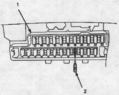

1. FUSE/RELAY BOX UNDER DASHBOARD

1. FUSE/RELAY BOX UNDER DASHBOARD
2. BACK UP FUSE (7.5A)


Final procedure


Note: This procedure should be performed after troubleshooting any faults.


1. Remove the jumper from the diagnostic connector.

2. Perform the ECM/PCM module reset procedure.

3. Enter the frequencies of the preset radio stations and set the time.

4. To re-enter the starting clutch control feedback signal into memory, refer to the relevant procedures below.

(The article was taken from the website: www.hondabook.ru)
This article is available at: russian, bulgarian, belarusian, ukrainian, serbian, croatian, romanian, polish, slovak, hungarian
This information has been verified: Emil Safonov
Share with friends:
◀ Previous
HR-V 1: Automatic gearbox
Next ▶

Voltage at the contacts of the PCM module — measurement conditions
Electrical diagram of the RCM module (automatic transmission control system)
Location of automatic transmission control components
Parking brake mechanism
General scheme of hydraulic pressure distribution
Table of fault codes
Linear control solenoids and locking solenoid
Speed sensors for the leading pulley, driven pulley and secondary shaft
Starter clutch control
Automatic transmission selector switch
See also other articles from Honda manuals:
Adjustment procedures Honda Accord 3 (1985-1989)
Troubleshooting Honda Civic 3 and 4 (1983-1991)
Troubleshooting the Radiator Fan Circuit Honda CR-V 2 (2002-2006, petrol)
Troubleshooting Honda Avancier 1 (1999-2003, petrol)
Link in different formats to this article
Comments and feedback from visitors
No comments yet


How much will 34 + 35 ?


HR-V 1 (1998-2006, petrol) 
  • General information
  • User manual
  • Maintenance
  • Power unit
  • Engine repair
  • Lubrication system
  • Cooling system
  • Fuel injection and control
  • Power and exhaust system
  • Engine electrical equipment
  • Transmission
  • Clutch
  • Mechanical gearbox
  • Automatic gearbox
  • Rear differential
  • Drive shafts and cardan
  • Chassis and running gear
  • Steering
  • Car suspension
  • Brake system
  • Body and interior
  • Exterior (external elements)
  • Interior (internal elements)
  • Doors, locks and windows
  • Electrical equipment
  • Equipment and devices
  • Lighting system
  • Electrical circuits
HondaBook.ru © 2018–2026 • Mobile version • Sitemap: EN BG BY UA RS HR RO PL SK HU • Feedback • Driver Information • Search system • Bookmark
Accord 3 (1985-1989) • Accord 6 (1997-2002) • Civic 3 and 4 (1983-1991) • Civic 5 and 6 (1991-2000) • Civic 6 (1995-2000) • Civic 7 (2000-2005) • Civic 8 (2005-2011) • Fit 1 (2001-2008) • CR-V 1 (1995-2001) • CR-V 2 (2002-2006) • HR-V 1 (1998-2006) • Avancier 1 (1999-2003) •
 
This website uses cookies to ensure proper functioning. By clicking "OK," you agree.