Contents: Testing signals at the indicator…⇊ Instrument cluster connector ⇊ Female connector on harness side ⇊
Testing signals at the indicator input
This area contains the Supplemental Restraint System (SRS) components. Review the SRS component locations, precautions, and procedures before performing repairs or maintenance.
1. Remove the instrument cluster assembly from the instrument panel (see Chapter. "Body"), then disconnect connectors A (22-pin) and B (16-pin) from the instrument cluster assembly.
2. Check if the connectors and contacts provide a tight connection.
3. If the contacts are bent, loose or rusted, correct the deficiencies and retest the system.
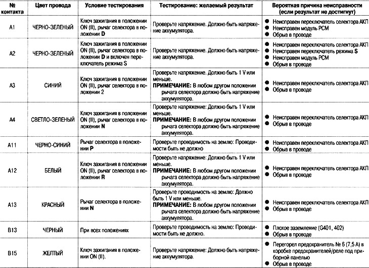
4. Test the following signals at the input of the A (22-pin) and B (16-pin) connectors of the instrument cluster.
5. If the input signal test is successful but the indicator is faulty, replace the printed circuit board.
Instrument cluster connector

Female connector on harness side