
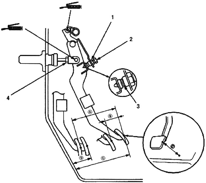
1. LOCK NUT A, 9.8 Nm (1.0 kgf/m)
2. ADJUSTING BOLT
3. PEDAL IN CONTACT WITH SWITCH
4. LOCK NUT B, 18 Nm (1.8 kgf/m)
A. (PEDAL TRAVEL): 130-140mm
IN. (TOTAL CLUTCH PEDAL FREE STROKE): 8-18mm including pedal play 1.0-9.0mm
WITH. (CLUTCH PEDAL HEIGHT):
left hand drive: 179 mm from the floor
right hand drive: 183 mm from the floor
D. (CLUTCH PEDAL HEIGHT FULLY DEPRESSED):
left hand drive: not less than 87 mm from the floor
right hand drive: not less than 74 mm from the floor
Note:
- For information on checking the clutch switch, see Sec. «Body electrical equipment».
- The clutch self-adjusts as it wears.
Warning! If there is no clearance between the clutch master cylinder piston and the push rod, the release bearing will press against the diaphragm spring, which can lead to slipping of the clutch and other problems.
1. Loosen locknut A and unscrew the clutch switch (or adjusting bolt), until it is no longer in contact with the clutch pedal.
2. Loosen lock nut B and screw in or out the push rod until you get the required travel (A) and height (WITH) clutch pedals.
3. Tighten locknut B.
4. Screw in the clutch switch (or adjusting bolt), until it comes into contact with the clutch pedal.
5. Tighten the clutch switch (or adjusting bolt) 3/4-1 turn.
6. Tighten locknut A.