
Testing the headlight range control switch
1. Remove the switch panel from the dashboard.
2. Disconnect the 5-pin connector from the switch.
3. Push the switch from behind the panel and remove it.
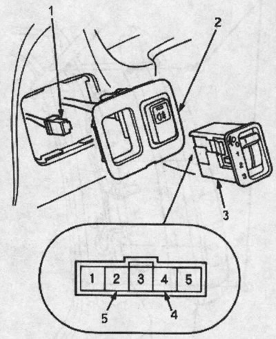
1. 5-PIN CONNECTOR
2. SWITCH PANEL
3. HEADLIGHT SWITCH
4. Not used
5. Not used
4. Measure the resistance between pins #1 and #3, then measure the resistance between pins #3 and #5 at positions 0,1,2 and 3 by moving the knob.
Between pins #1 and #3: About 4.7 kΩ
Between pins #3 and #5:
| Handle position | 0 | 1 | 2 | 3 |
| Resistance, kOhm (approximately) | 3,9 | 3,5 | 2,8 | 2,4 |
5. If resistance differs from specified, replace the switch.
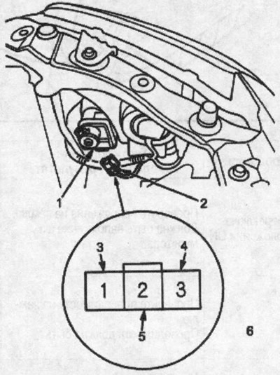
1. HEADLIGHT ELECTRIC CORRECT UNIT
2. 3-PIN CONNECTOR
3. BLACK AND YELLOW
4. BLACK
5. BLUE YELLOW
6. Connector «Mother» from the harness side
2. Check for continuity between pin #3 (BLACK WIRE) and mass. Conductivity should be
- If there is no continuity, check:
- Is there an open in the BLACK wire.
- Bad grounding (G201, G202, G301).
- If there is conductivity, go to p.Z.
3. Check the voltage between pin #1 (BLACK-YELLOW WIRE) and ground when the ignition key is in the ON position (II). There should be battery voltage.
- If there is no battery voltage, check for an open in the BLACK/YELLOW wire.
- If there is battery voltage, go to step 4.
4. Check for continuity between pin #2 (BLUE-YELLOW WIRE) and ground in all switch positions. Conductivity should be
- If there is no continuity, check:
- If there is continuity, go to step 5.
- Is there an open in the BLUE-YELLOW wire.
- Is the headlight dimmer switch OK?
- If there is conductivity, proceed to cp. 5.
5. If all checks show the norm, but the headlight electrocorrector does not work, check if it is frozen, stuck, if the headlight electrocorrector unit is installed correctly. If the mechanical part is normal, replace the headlight electric corrector unit.
6. After installation, recheck the system.