Testing the signal at the input of the control unit
1. Disconnect the 5-pin connector from the rear fog light control unit.
2. Check the pins of the connector and socket and make sure they make good contact (figure and table below).
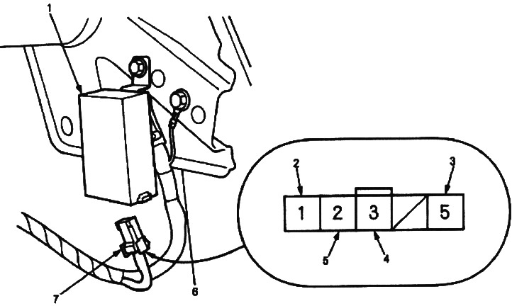
1. REAR FOG LIGHT CONTROL UNIT
2. RED-BLUE WIRE
3. BLACK WIRE
4. RED-GREEN WIRE
5. RED-YELLOW WIRE
6. Connector «Mother» from the harness side
7. 5-PIN CONNECTOR

If the contacts are bent, loose, or rusted, repair and recheck the system.
- If the pins appear to be OK, perform the following checks on the connector.
- If any of the checks indicate a problem, find and correct the cause, then recheck the system.
Circuit breaker testing
1. Remove the switch panel from the dashboard.
2. Disconnect the 6-pin connector from the rear fog light switch.
3. Push the switch from behind the panel and remove it.
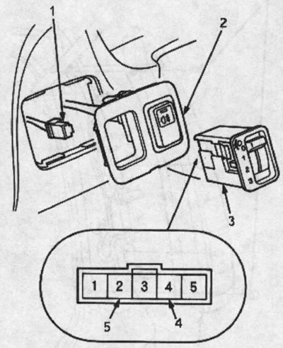
1. 5-PIN CONNECTOR
2. SWITCH PANEL
3. HEADLIGHT SWITCH
4. Not used
5. Not used
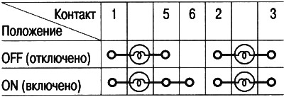
4. Check the presence of continuity between the contacts in all positions of the switch in accordance with the table.
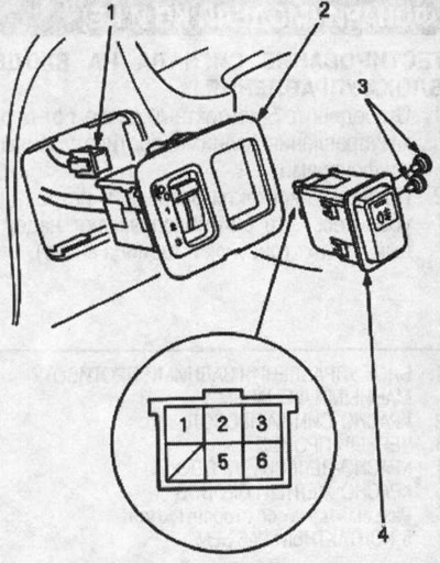
1. 6-PIN CONNECTOR
2. SWITCH PANEL
3. LIGHT BULBS (0.91 W)
4. REAR FOG LAMP SWITCH