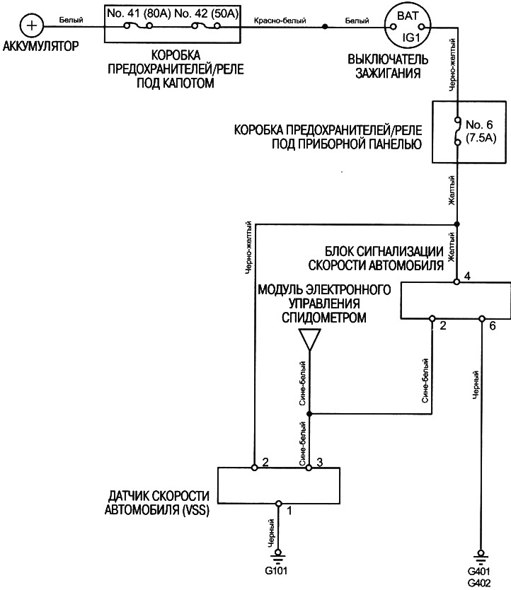
Testing the vehicle speed alarm unit
Note: Before testing, check fuse #6 (7.5A) in the under-dash fuse/relay box.
1. Carefully remove the lower instrument panel cover.
2. Check for conductivity between contact #6 and ground. There should be conductivity.
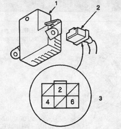
1. vehicle speed alarm unit; 2. 6-pin connector; 3. female connector on the harness side
- If there is no conductivity, check:
- Is there a break in the BLACK wire?.
- Poor grounding (G401, G402).
- If there is conductivity, proceed to step 3.
3. Check for voltage between terminal #4 and ground when the ignition switch is in the ON (II) position. There should be battery voltage.
- If there is no voltage, check for a break in the YELLOW wire.
- If there is battery voltage, proceed to step 4.
4. With the ignition key turned to the OFF position, reconnect the 6-pin connector to the speed alarm unit and connect the voltmeter to pin #2.
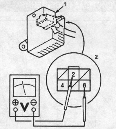
1. vehicle speed alarm unit; 2. female connector on the harness side
5. Raise the vehicle and securely support it on the safety stands at the designated points.
6. Turn the ignition switch to the ON (II) position again and slowly rotate the front wheel, then check that the voltmeter needle moves alternately from 0 V to approximately 5 V or more, and then from 5 V or more to 0 V.
If there is no voltage, check:
- Vehicle Speed Sensor (VSS) (see above).
- Is there a break in the BLACK-BLUE wire?.
7. If the vehicle speed sensor (VSS) is normal, replace the vehicle speed alarm unit.
Vehicle Speed Alarm System Wiring Diagram (KY Model)