
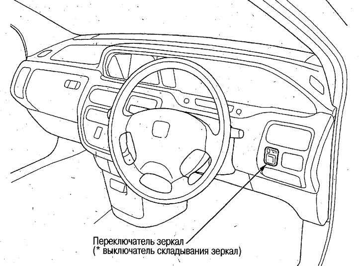
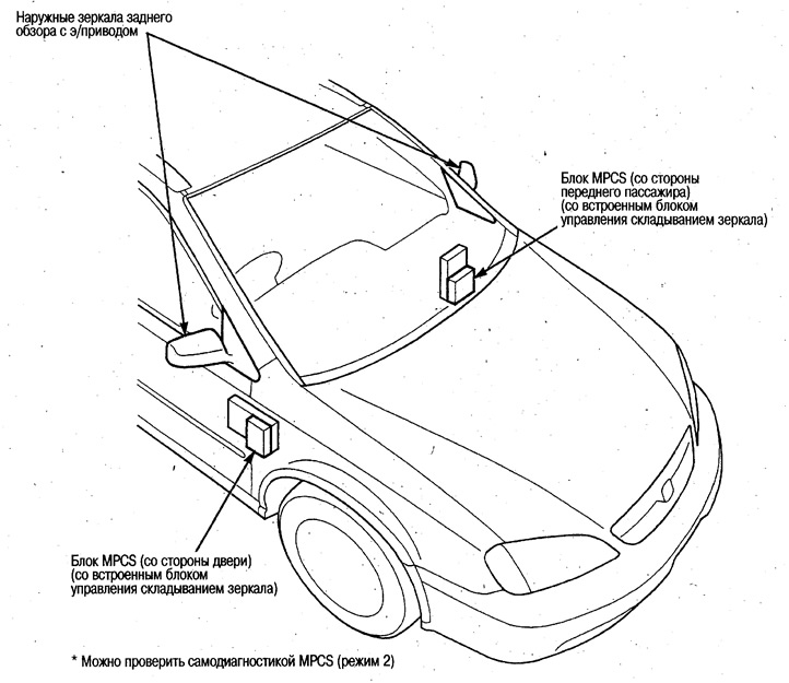
Component Locations
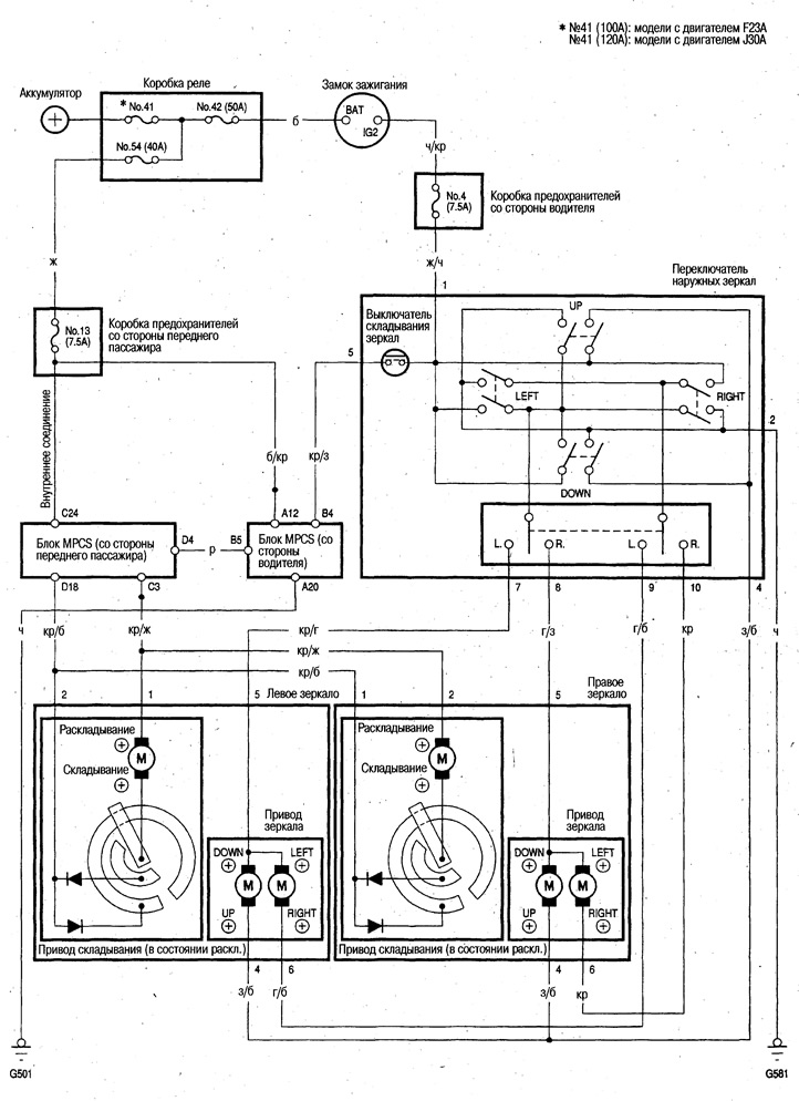
Electrical diagram
Examination
Before checking, make sure that fuse No.4 (7.5A) in the driver's side fuse box is in good condition and securely connected.
1. Remove the driver's side deflector (see chapter Body).
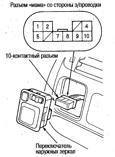
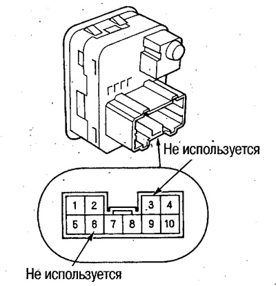
2. Disconnect the 10-pin connector from the window switch.
When the left and right mirror drives do not work
3. Turn the ignition key to the ON (II) position and check the voltage between terminal No.1 and ground.
If there is no voltage, perform the following check: Check the yellow-black wire for a break and the reliability of the contact connections.
If there is battery voltage, proceed to the next test.
4. Check the conductivity between contact No.2 and ground.
If there is no continuity, perform the following check: Check the black wire for a break and the reliability of the contact connections. Quality of the "ground" (G581).
If there is continuity, replace the switch.
When the left mirror drive does not work
5. Short contacts #1 and #7 together and contact #4 (or #9) to ground. Turn the ignition key to the ON (II) position and check if the left mirror turns down (or to the left).
If the mirror does not turn down (or left), check the green-white (or blue-white) wire for a break and a secure connection of the contacts. If everything is OK, check the left mirror drive.
If the mirror does not turn down and to the left, check the red-blue wire for a break and the reliability of the contact connections.
If the mirror rotates down and to the left at the same time, check the mirror switch.
When the right mirror drive does not work
6. Short contacts #1 and #8 together and contact #4 (or #10) to ground. Turn the ignition key to the ON (II) position and check if the right mirror turns down (or to the left).
If the mirror does not turn down (or left), check the green-white (or red) wire for a break and for a secure connection. If everything is OK, check the right mirror drive.
If the mirror does not turn down and to the left, check the blue-green wire for a break and the reliability of the contact connections.
If the mirror rotates down and to the left at the same time, check the mirror switch.
When the mirror folding drives do not work
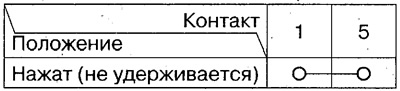
7. Turn the ignition key to the ON (II) position. Close and open contacts No.1 and No.5 and check whether the left and right mirrors fold and unfold.
If the mirrors do not fold or unfold, check the input signals to the MPCS unit on the front passenger side.
If the mirrors fold and unfold, replace the switch.
Checking the switch
1. Remove the mirror switch.
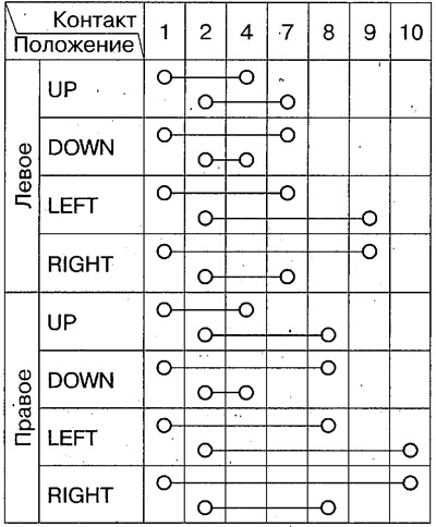
2. Check the continuity between the various contacts in each switch position and make sure that there is continuity only between the contacts connected by the lines in the table.
Exterior mirror switch
Mirror folding switch
 |
 |
Checking the drive
1. Remove the mirror trim and door trim (see chapter Body).
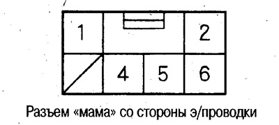
2. Disconnect the 6-pin connector from the mirror.
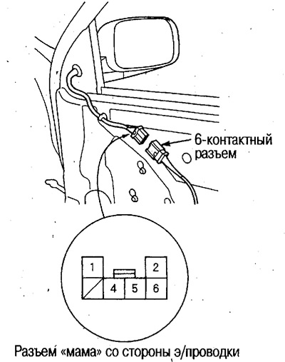
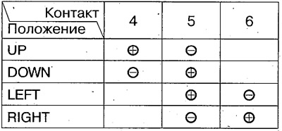
3. Check the smooth operation of the mirror after applying voltage from the battery to the contacts indicated below.
Mirror drive
Folding drive
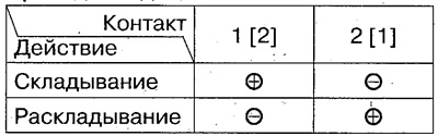
[]: left mirror
Replacing the mirror drive
Removal
1. Remove the mirror assembly (see chapter Body).
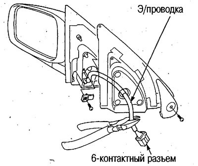
2. Disconnect the 6-pin mirror electrical wiring connector and cut the electrical wiring with wire cutters.
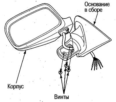
3. Unscrew 3 screws and separate the mirror base from the housing.
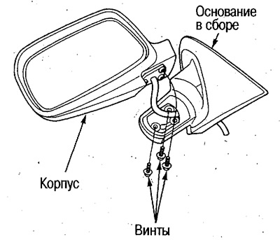
4. Remove the mirror holder from the housing.
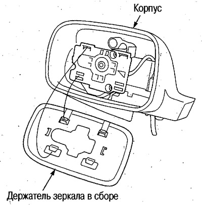
Caution: To avoid damaging the mirror and body, use a cloth.
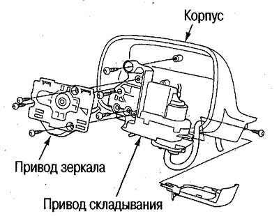
5. Unscrew all screws and remove the drive from the housing.
Installation
6. Install the drive assembly onto the housing.
Do not deform the contacts when passing the wire through the hole. Wrapping the contacts together with vinyl tape will make the job easier.
Use new screws, do not overtighten them.
7. Install the mirror holder assembly onto the drive.
Attention.
- To prevent the mirror from breaking, hold it with your palm during installation.
- Make sure the mirror is installed correctly.
8. Pass the electrical wiring through the hole in the base and install the housing on the base.
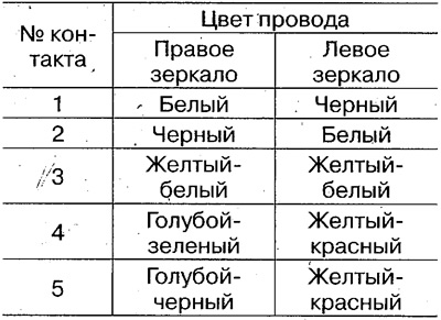
9. Insert the electrical wiring contacts into the new connector, looking at the wire arrangement of the cut connector.
 |
 |
10. After installing the mirror, check the operation of the mirror and the absence of extraneous sounds by operating the switches several times.
(Original published on this resource: Hondabook.ru)