
Contents: Checking the right and left rear…⇊ Checking the mirror adjustment switch ⇊ Checking the electric drives for…⇊
Checking the right and left rear view mirrors
Note: Before starting this test, check the fastening of the fuses in fuse box #22 (7.5 A).
1. Remove the mirror adjustment switch (A).
2. Disconnect the "13P" (B) connector from the switch.
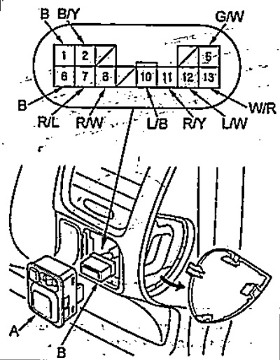
If the adjustment actuator does not function "right/left"
3. Turn on the ignition and check for conductivity between terminal "2" of the connector and ground.
a) If the voltage does not match the battery voltage, the "B / Y" wire is damaged.
b) If the voltage matches the battery voltage, follow the next step.
4. Check for conductivity between terminal "6" of the connector and ground.
a) If there is no conductivity, the wire "B" is damaged or the "ground" (G401) is faulty.
b) If there is conductivity, check the switch.
If the left rearview mirror electric drive does not function
5. Make sure that there is a short circuit between terminals "2" and "10", "5" (or "12") and "ground".
Turn on the ignition and press the "DOWN" (or "LEFT") side of the switch and make sure that the mirror turns in the specified direction.
- If the mirror does not perform the specified operation, check if the wires or connector ("L/B") are damaged,
- If the wires and connector are OK, check the right mirror electric drive. If the mirror performs the specified operation, check the switch.
If the electric drive of the right rearview mirror does not function
6. Make sure that there is a short circuit between terminals "2" and "11", "5" (or "13") and "Ground".
Turn on the ignition and press the "DOWN" (or "LEFT") side of the switch and make sure that the mirror turns in the specified direction.
- If the mirror does not perform the specified operation ("DOWN" (or "LEFT"), check if the wires or connector ("G/W" or "W/R") are damaged.
- If the wires and connector are normal, check the left mirror electric drive. If the mirror does not perform both operations ("DOWN" and "LEFT"), check the wires and connector ("R / Y").
- If the mirror performs the intended operation, check the switch.
If the electric drive for adjusting the mirror housing does not function.
7. Make sure that there is a short circuit between terminals "2" and "7", "8" and "ground".
Turn on the ignition and make sure that the electric drives for adjusting the right and left mirror housings are functioning.
8. Make sure that there is a short circuit between terminals "2" and "8", "7" and "ground".
- Turn on the ignition and make sure that the electric drives for adjusting the right and left mirror housings are functioning.
- If the body performs the intended operation, check the switch.
Checking the mirror adjustment switch
1. Remove the instrument panel from the driver's side.
2. Remove the switch (A) and disconnect the "13P" connector (B).
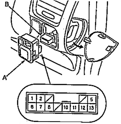
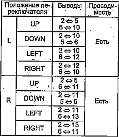
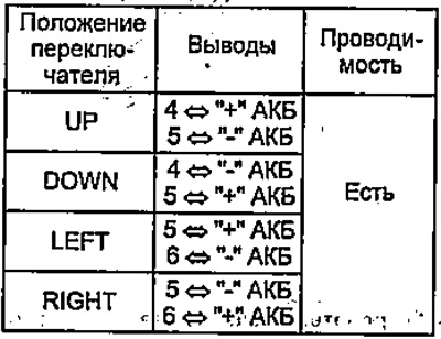
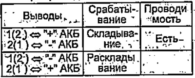
3. Check the conductivity between the terminals in each switch position as shown in the table.
Mirror adjustment switch.
Folding switch.

Checking the electric drives for adjusting the position of the right and left mirrors.
1. Remove the door trim.
2. Disconnect the "6P" connector (A) from the mirror.
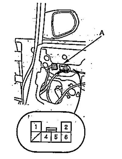
3. Apply battery voltage to the connector terminals as shown in the table and make sure the electric motor rotates slowly.
Electric mirror drive.
Electric folding mirrors.
* - electric drive of the left mirror.
(Publication reprinted from the website: www.HondaBook.ru)