
Shift Lever Cover Assembly
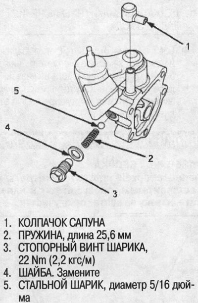
1. Unscrew the breather cap and the ball lock screw, remove the washer, spring and steel ball.
2. Unscrew the special bolt and remove the conical spring washers.
3. Remove the shift lever, linkage C and thrust washer from the shift rod linkage cover.
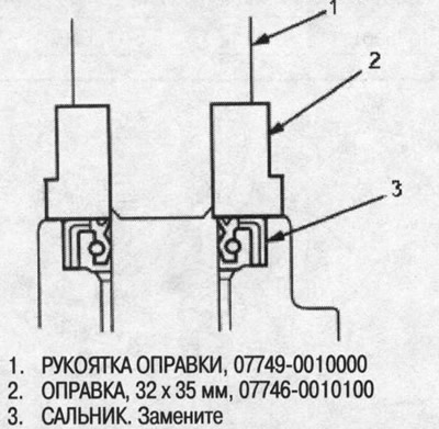
4. Remove the oil seal.
Note: When installing, turn the thrust washer with the alloy surface facing the shift linkage cover.
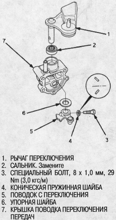
5. Installation is carried out in the reverse order of removal.
Gear shift lever shaft assembly
1. Unscrew the special bolts and remove the conical spring washers.
2. Remove the retainer, gear shift rods A and B from the axle.
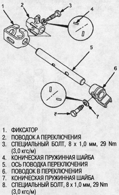
3. Installation is performed in the reverse order of removal.
Checking the gaps
1. Measure the gap between shift rod A and gear selector rod.
- Standard (new): 0.05-0.25 mm
- Limit: 0.5 mm
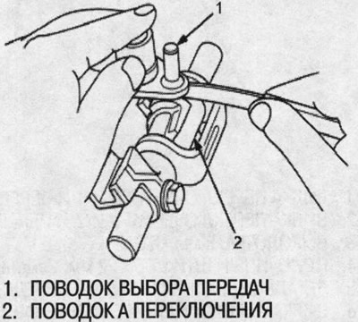
2. If the clearances exceed the specified limits, measure the diameter of the gear selector pin.
- Standard: 7.9-8.0mm
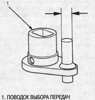
If the diameter of the gear selector pin is less than the limit value, replace the pin with a new one.
If the pin diameter is within the normal range, replace the shift linkage A with a new one.
3. Measure the gap between gear shift lever B and gear shift lever C.
- Standard (new): 0.05-0.25 mm
- Limit: 0.5 mm
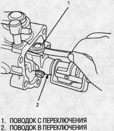
4. If the gaps exceed the specified limit, measure the diameter of the shifter pin C.
- Standard: 12.9-13.0 mm
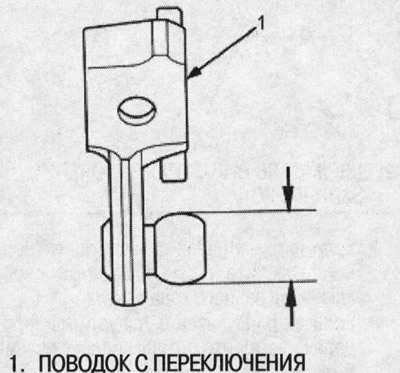
If the diameter of the gear shift rod C is less than the limit value, replace the gear shift rod C with a new one.
If the diameter of the gear shift rod C is within the normal range, replace the gear shift rod B with a new one.
[The original is located on the website: Hondabook.ru]