
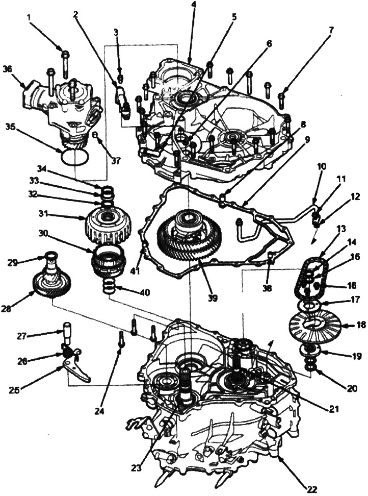
1. 10x1.25 mm, 3 bolts
2. ATF SUPPLY PIPE HOLDER ASSEMBLY
3. 6x1.0 mm, 2 bolts
4. FLYWHEEL CASE
5. CONNECTOR BRACKET
6. O-RING. Replace
7. FLYWHEEL CASE MOUNTING BOLTS, 18 bolts
8. REFERENCE PIN
9. FLYWHEEL CASE GASKET. Replace
10. ATF SUPPLY PIPE ASSEMBLY
11. 6x1.0 mm, 1 bolt
12. O-RING. Replace
13. ATF PUMP DRIVE CHAIN
14. RETAINING RING
15. THRUST GASKET, 22x28 mm. Selected on site 16.6x1.0 mm, 3 bolts
17. ATF PUMP DRIVE SPROCKET
18. PITO FLANGE
19. ATF PUMP DRIVE SPROCKET HUB
20. THRUST WASHER
21. DRIVE SHAFT
22. GEARBOX CASE
23. DRIVE PULLEY SHAFT
24. FLYWHEEL CASE MOUNTING BOLT 3 bolts
25. PARKING BRAKE LATCH
26. PARKING BRAKE LATCH SPRING
27. PARKING BRAKE LATCH AXLE
28. SECONDARY SHAFT
29. ADJUSTING GASKET, 25x35 mm. Selected on site
30. SECONDARY SHAFT DRIVE GEAR ASSEMBLY
31. STARTER CLUTCH ASSEMBLY
32. CROUTONS, 25.5 mm. Selected on site
33. CROUTON HOLDER
34. RETAINING RING
35. O-RING. Replace
36. TRANSFER CASE ASSEMBLY (4WD)
37. REFERENCE PIN
38. REFERENCE PIN
39. DIFFERENTIAL ASSEMBLY
40. O-RING. Replace
41. REFERENCE PIN
Note:
- The picture shows a 4WD gearbox; the 2WD transmission does not have a transfer case assembly or components related to the transfer case.
- Clean all parts thoroughly with solvent or carburetor cleaner and dry with compressed air.
- Blow out all channels.
- When removing the transmission housing/flywheel housing, replace the following:
- O-ring seals
- Starter clutch assembly
- Secondary shaft drive gear assembly
- Flywheel housing gasket
1. Remove the transfer case assembly from the transmission on 4WD models.
2. Remove the ATF feed tube holder assembly.
3. Unscrew the flywheel housing mounting bolts:
- 18 bolts on the flywheel housing side.
- 3 bolts on the gearbox housing side.
4. Remove the flywheel housing.
5. Remove the ATF pump drive sprocket (three bolts), then remove the ATF pump drive chain.
6. Slide the pitot flange towards the cutout, then remove the pitot flange.
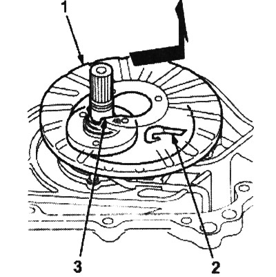
1. PITO FLANGE
2. PITO TUBE
3. CUTOUT
7. Remove the snap ring securing the ATF pump drive sprocket hub, then remove the 22 x 28 mm thrust shim, ATF pump drive sprocket hub and thrust washers.
8. Remove the differential assembly.
9. Remove the latch shaft, latch spring and parking brake latch.
10. Remove the retaining ring securing the starting clutch, then remove the cracker holder and crackers.
11. Attach the special tool to the starting clutch and securely hook the special tool jaws onto the parking gear as shown in the figure.
Warning!
- Do not insert the special tool grips into the starting clutch guide, otherwise the guide may be damaged.
- Prevent dust and other foreign objects from entering the driven pulley shaft.
12. Using the special tool, remove the starting clutch and secondary shaft drive gear assembly, then remove the secondary shaft.
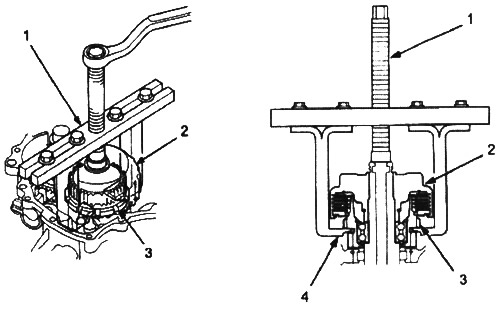
1. STARTER CLUTCH PULLER, 077TAE-P4V0120
2. STARTER CLUTCH ASSEMBLY. Replace
3. PARKING GEAR
4. CAPTURE
The article was copied from the website www.HondaBook.ru