How to start troubleshooting
When the malfunction indicator lamp lights up (MIL), check the diagnostic trouble code (DTC) in the following way:
Note: This operation can also be performed using a Honda PGM tester connected to (5-pin gnome) data connector.
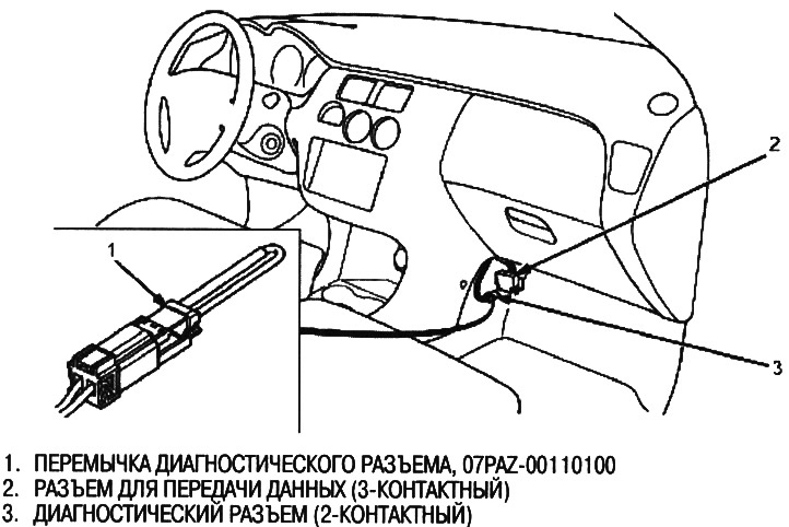
1. Place a jumper in the diagnostic socket as shown in the figure. (The 2-pin diagnostic connector is located under the dashboard on the passenger side). Turn the ignition key to the ON position (II).
The illustration below shows a left-hand drive model; the location on the right-hand drive model is symmetrical.
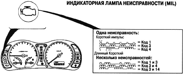
2. Write down the diagnostic trouble code (DTC); The MIL will give a code that varies in length and number of flashes, the MIL may indicate multiple faults by displaying individual codes one after the other. Codes 1 to 9 are indicated by separate short flashes. Codes from 10 to 65 are indicated by a series of long and short flashes. The number of long flashes indicates the first digit, the number of short flashes indicates the second. Sometimes the first flash is harder to see; always read the flashes at least twice to check the code.
Engine/Power Train Control Module Reset Procedure (ECM/PCM)
Note: This operation can also be performed using the Honda PGM tester.
1. Turn the ignition key to the OFF position.
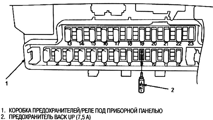
2. Pull out the BACK UP fuse for 10 seconds (7.5 A) from the under-dash fuse/relay box and reset the ECM/PCM.
The illustration shows a left-hand drive model; the location on the right-hand drive model is symmetrical.
Final procedure (should be performed after troubleshooting any problem)
1. Remove the jumper from the diagnostic socket.
Note: If a jumper is left in the diagnostic connector when no DTCs are stored in the ECM/PCM, when the ignition switch is turned to the ON position, (II) MIL will be on
2. Perform the ECM/PCM reset procedure.
Substitution of a known-good ECM/PCM (models KG, KE, KQ, KU, KN)
If you require a known-good ECM/PCM to test your vehicle, use the following procedure. It allows you to transfer such a module from a donor car without the need to program it for the ignition key of the tested car.
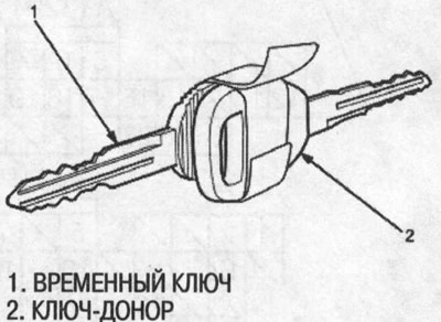
1. Make a temporary ignition key for the test vehicle from a blank without an immobilizer chip.
2. Remove the ECM/PCM from the vehicle under test.
3. Write down the VIN of the vehicle you are testing on the ECM/PCM you just removed so you don't frighten it with the donor vehicle's module.
4. Remove a known-good ECM/PCM from the donor vehicle and install it in the vehicle being tested.
5. Tape the ignition key of the donor vehicle to the temporary key of the vehicle under test, head to head. The ECM/PCM will then recognize the key code of the donor vehicle and allow you to start the engine with the temporary key.
6. After completing the checks, reinstall both ECM/PCMs and destroy the temporary key.
Removing the ECM/PCM
If any code-based diagnostic requires voltage or resistance checks at the ECM/PCM connectors, remove the glove box, passenger side door sill molding, and wheel arch panel. Loosen the ECM/PCM cover bolts. Perform a system check following the procedure for these DTCs on the following pages.
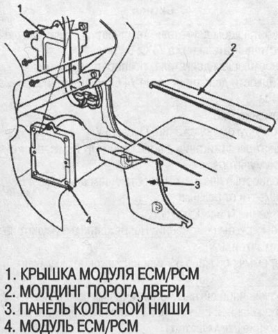
The illustration shows a left-hand drive model; the location on the right-hand drive model is symmetrical.
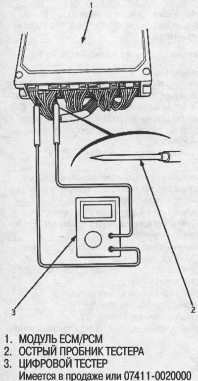
Checking contacts in the connectors of the ECM / PCM module
When checking the pins in the ECM/PCM connectors, carefully insert the tester's sharp probe into the harness side of the connector until it touches the contact portion of the wire.